
Installation Owner's manual


TeamWork • Installation Guide (Continued)
4
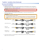
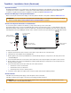
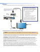
Cabling
0.5A M
AX
POWER
12V
1
2
B
A
3
4
5
6
INPUTS
MPS 601
CONTACT IN / TALLY OUT
HDMI
RGBHV
HDMI
HDMI
RS-232
GC
1 3 5
2 4 6
T T
C G TC G
G
C T TC
G T
+V
C G
Tx Rx G
OUTPUT
REMOTE
Extron
SHARE
100-120V 50/60Hz
12A MAX POWER OUTPUT 12A MAX
LAN
COM
TX
IN S G
+5VRX
INPU
T
IR
US
LIS
TED
1
7TT
AU
DIO/
V
ID
EO
A
PA
RATUS
®
Extron
Cable Cubby 800
Cable Access Enclosure
1
00-240
V
/
5A
M
A
X
1
00-240V
/
5A
MA
X
10
0-
240V/
5A MA
X
Regional Sa
les
0
30
60
90
120
150
SOUTH
NORTH
EAST
WEST
Extron
MPS 601
Switcher
Extron
IPL T PC1
System Controller
RS-232
Control Cable
HDMI
VGA
Extron
HDMI Pro Cable
HDMI Video
Flat Panel
Display w/ Integrated
Speakers
Extron “Show Me” Cables
Flat Panel
AC Cord
Contact Closure
& Tally
Regional Sales
0
30
60
90
120
150
SOUTH
NORTH
EAST
WEST
HDMI
HDMI
HDMI
VGA
13
2
1
4
5
6
6
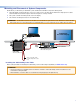
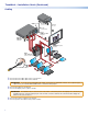
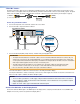
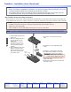
a Connect the “Show Me” cables to the source devices.
b Connect the “Show Me” cables to the switcher.
ATTENTION: If you have analog and digital video inputs, ensure that your TeamWork switcher can accept both types of
signal. If not, you need the VGA TeamWork kit to convert the analog signal.
c Connect the switcher to the display.
d Connect the display to the system controller.
ATTENTION: The illustration above shows the IPL T PC1, which controls AC power to the display. The controller in your
TeamWork kit may control the display by IR or RS-232 and connections between the controller and the display will
differ from those shown above.
e Connect the system controller to the switcher.
f Connect power to the switcher and system controller.