Installation Guide Architectural Connectivity TLP 350CV TouchLink 3.5” Cable Cubby Touchpanel ™ ® 68-1692-01 Rev.
Precautions Safety Instructions • English Warning This symbol is intended to alert the user of important operating and maintenance (servicing) instructions in the literature provided with the equipment. Power sources • This equipment should be operated only from the power source indicated on the product. This equipment is intended to be used with a main power system with a grounded (neutral) conductor. The third (grounding) pin is a safety feature, do not attempt to bypass or disable it.
FCC Class A Notice This equipment has been tested and found to comply with the limits for a Class A digital device, pursuant to part 15 of the FCC Rules. Operation is subject to the following two conditions: 1. This device may not cause harmful interference. 2. This device must accept any interference received, including interference that may cause undesired operation.
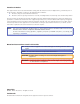
Contents Introduction ............................................ 1 Initial Configuration............................... 12 About This Guide.............................................. 1 About the TLP 350CV....................................... 1 Features............................................................ 2 Requirements.................................................... 4 Hardware and Software................................ 4 Control Interface...........................................
TLP 350CV • Contents vi
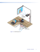
Introduction zz About This Guide zz About the TLP 350CV zz Features zz Requirements About This Guide This guide describes the function, installation, configuration, and operation of the TLP 350CV touch panel controllers. About the TLP 350CV The Extron TLP 350CV TouchLink™ 3.5” Cable Cubby® Touchpanel combines A/V system control with cable management.
Features TLP 350CV features include: 3.5 inch LCD screen — displays a wide range of customizable graphics. Touch screen overlay — provides simple and intuitive control over a range of functions by touching on-screen icons. Built-in speaker — provides audible feedback when a button is pressed. Ten buttons — for common, user-defined functions. Pre-labeled buttons are available to customize panel operation. Light sensor — allows auto dimming feature to adjust LCD screen backlighting to ambient lighting.
Extron TLP 350CV 3.
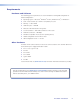
Requirements Hardware and Software The following system requirements are recommended for running GUI Configurator or Global Configurator 3: zz Operating System – Microsoft® Windows® XP SP2, Windows Vista®, or Windows 7 zz CPU – Intel® Pentium® III, 1.0 GHz or compatible processor zz Memory – 1 GB of RAM zz Hard Disk space – 100 MB zz Microsoft .NET Framework 2.
Preparing the Table This section includes the following topics: zz Installation Overview zz Cutout Dimensions Installation Overview Planning zz Determine the optimum furniture location for the TLP 350CV keeping in mind the following: zz the size of the enclosure that will be below the table, zz the orientation of the touch-screen for ease of viewing, zz the reach distance for a user for convenient operation, zz clearances for under-table cabling, zz the location of devices that may be connecte
Cutout Dimensions Cutout dimensions are available from Extron as a router guide, printed dimensions for a CNC wood router, and a paper cutout template for a reciprocating saw or jigsaw. If using the router guide, follow the instructions included with it. Printed dimensions are available in Specifications on page 36. The opening in the table for the Cable Cubby should be cut only by licensed and bonded craftspeople. Exercise care to prevent scarring or damaging the furniture.
Mounting the Enclosure This section includes the following topics: zz Installing the Power Module, Cables and AAPs zz Mounting the Enclosure Installing the Power Module, Cables and AAPs Each TLP 350CV includes pass-through AAPs and a power module. A wide range of passive AAPs are also available allowing direct connection of cables from the top and underneath the AAPs. See www.extron.com for passive AAP options. Shelf brackets are available in two-space and three-space configurations.
Install the Power Module and Shelf Assemblies NOTE: The included power module takes up two (US) or three (Int’l) AAP spaces and must be installed on the left side of the TLP 350CV enclosure. Install the power module and AAP assembly into position at the desired location and elevation. Secure with the included #4-40 Phillips head screws. 1 Install the power module on the left side. 3 Philips head screws secure AAP shelf assembly and power module. Large holes provide tool access to fasten rear brackets.
Mounting the Enclosure CAUTION: The trim ring edges can easily be nicked or bent. Exercise caution when handling and mounting the enclosure. 1. Remove the edge grommet protecting the corners of the trim ring and the plastic film on the finished surfaces. CAUTION: Do not use isopropyl alcohol or other solvents to clean the Cable Cubby. Strong solvents may ruin some finishes. 2.
Connecting the Touch Panel This section includes the following topics: zz Connecting the TLP 350CV zz Mounting the Power Supply (US models only) Connecting the TLP 350CV The rear panel of the TLP 350CV located on the bottom of the enclosure, provides all required connections. The panel requires an IP Link controller for operation, but may be configured without one connected. UTP or STP CAT5 or better cable.
CAUTION: Always use a power supply supplied or specified by Extron for use with the TLP 350CV. Use of an unauthorized power supply voids all regulatory compliance certification and may cause damage to the supply and the TLP 350CV. Unless otherwise stated, the AC/DC adapters are not suitable for use in air handling spaces or in wall cavities.
Initial Configuration This section provides information on the front panel controls and indicators, the on-screen menus used to configure the TLP 350CV, and calibration of the touchscreen. zz Front Panel Controls and Indicators zz Configuring the TLP 350CV (Initial Setup) zz Internal On-screen Menus zz Touchscreen Calibration Front Panel Controls and Indicators The front panel provides control and operation via the touch screen, the side buttons, and speaker. a d b e f g h c Figure 5.
c d Speaker — Provides audio feedback of button or panel presses. e Menu Button (under faceplate) — A menu button is used to configure system and display preferences. Configurable Side buttons — 10 dedicated, customizable function buttons provide quick access to key functions. A set of 6 buttons with alternative labels is included with the TLP 350CV. There are also additional titles available.
Main Menu Provides adjustment of the sleep timer and touchpanel brightness (backlight), and LED backlight operation for the side buttons. Sleep Timer Sleep mode is activated when there has been a period (0 to 50000 seconds) of inactivity. The backlight is switched off and the touch screen goes dark. Adjust the sleep timer from 0 to 50000 seconds by pressing the Down or Up buttons. Sleep mode is overridden by user interaction with the touch screen or side buttons.
Volume Control The Volume Control menu allows the user to adjust the maximum volume of the sound, individual volume of button click feedback, and audio playback. Pressing main returns you to the main setup screen. Master Volume Master volume defines the maximum volume for all playback. All other volume settings will be scaled in proportion.
IP (Network) The IP configuration menu displays network-related parameters. MAC 00-05-A6-05-7D-A6 IP Address This text box displays the currently configured IP address for the panel. To change the IP address: IP Address 192.168.254.254 Subnet Mask 1. Press the on-screen IP address box. A new screen appears with a number pad. 255.255.000.000 2. Enter the desired IP address in the format: xxx.xxx.xxx. xxx. DHCP Main Off 3.
Video The video menu adjusts the appearance of a video signal connected to the video inputs.
Configuration Software The section provides information on the following topics: zz Configuration and Control Software zz Installing Software zz Using the TouchLink Panel Web Pages zz Using GUI Configurator zz Using Global Configurator Configuration and Control Software Designing a graphical user interface (GUI) for the TouchLink panel takes two steps: zz Design the layout of the text and graphics. (See Using GUI Configurator on page 22.) zz Assign functions to the text and graphics.
If required, locate the Global Configurator program on the disc or Web site and install that also. By default, the Installer program creates and places the Global Configurator program in the C:\Program Files\Extron\GCx.x folder, where x.x represents the version of the Global Configurator program. During installation, there is an option to place an icon on the Windows desktop. Both programs can be downloaded from the Extron Web site (www.extron.com).
Figure 8. System Settings 3. Selecting Passwords allows the user to set passwords for an Administrator and a User. To set a password, follow the instructions at the top of the page. Figure 9. Passwords 4. To upgrade the unit’s firmware, select Firmware Upgrade. More detailed instructions are found in the “Updating Firmware from a Browser” section on page 17. 5. Click on the Touchpanel tab, which allows the user to alter the Touchpanel and volume settings.
Figure 10.
Using GUI Configurator This section provides an overview of the GUI Configurator program. For complete information about the program, consult the GUI Configurator Help File (select Contents in the Help Menu or press the F1 key while within the program). NOTE: To configure the TLP 350CV, use GUI Configurator version 1.1 or later. To use the GUI Configurator program, follow these instructions: 1. Click on the desktop icon.
Figure 12. GUI Configurator Start Options Dialog Box 2. You can choose to: zz Start a New Project — Clicking OK opens a dialog box that offers a choice of project options. Figure 13. GUI Configurator New Project Dialog Box A series of icons offer the choice of creating a project with or without a template and allows you to select the size and type of Touchlink panel. If you are creating a project from an existing template, you can use the factory-loaded templates or select a previously created template.
zz Open an Existing Project — Clicking OK opens a dialog box that allows you to navigate to an existing project for modification. Figure 14. GUI Configurator Dialog Box to Open an Existing Project Navigate to the existing file and select it. A preview with information about the file appears in the pane on the right. If you will be working on the project, leave the “Open as read-only” box unchecked. Click Open to open the file. The project will open in GUI Configurator.
3. Depending on which option was selected in step 2, GUI Configurator opens to a new or an existing project. The initial screen is divided into a series of panes offering a range of tools that can be used to design or modify the project. For full details on how to use these tools, consult the help file (in the Help menu click on Contents or press the F1 key while within the program). Figure 16. GUI Configurator Main Screen 4. To save the project, select Save Project from the File menu.
b. The Panel Manager dialog box opens: Figure 18. Add a TouchLink panel (5b) c. Click on the Add Panel Icon to add a new panel to the list in the left pane. d. Highlight the name of the panel in the left pane to display the properties of that panel in the right pane. e. When a new panel is added, it has the default IP address (192.168.254.254). To change the IP address, highlight the address property in the right pane and type in the correct IP address. Update any other properties, as required. f.
Using Global Configurator NOTE: To configure the TLP 350CV, use Global Configurator version 3.0.4 or later. This section provides an overview of the Global Configurator program. For complete information about the program, consult the Global Configurator help file (click on Contents in the Help menu or press the F1 key while within the program). This section describes how to set up Global Configurator project with an IPL 250.
Figure 20. Global Configurator Project Settings 3. Enter the IP Address for the TLP 350CV panel. The default Telnet connection is port 23 and HTTP is port 80, so these values do not usually need to be changed. If necessary, set Administrator and User passwords. If required, set the date and time. Checking the “Set Device as GlobalViewer Host” box is optional.
4. Click OK and the Project Settings screen closes and is replaced by the “Add Device” dialog box: Figure 21. Global Configurator Add Device Dialog Box To see all the options, click on the “Advanced >>>“ button. The button name changes to “Basic <<<“ (as shown in the figure above). a. Select the IP Link device from the drop-down menu. In figure 32, above, an IPL 250 controller is added. Adding a different IP Link product will be similar. b. Enter the IP address of the IP Link controller.
5. Click OK and the Add Device screen closes. The start-up screen, which was behind it, is now visible, showing the IPL 250 and the available ports: Figure 22. Configuring an IP Link Device 6. Select Touchpanel Port 1. The screen shows the available options for the TouchLink panel. To add the GUI Configurator project that was uploaded to the TouchLink panel, click “Click here to add one.” Figure 23.
7. The “Add TouchPanel” dialog box opens. Figure 24. Add Touchpanel Dialog Box a. Ensure the TouchLink panel model is selected from the drop-down menu and enter the IP address. b. Set the Telnet Port (usually 23) and, if necessary, enter the password. c. Check the “Import/Apply Layout” box and click OK. 8. The window now shows the GUI from the TouchLink panel. Figure 25. Touchpanel GUI Loaded Onto Global Configurator 3 9.
Reference Information zz Specifications zz Product Dimensions zz Part Numbers (Included parts) zz Accessories (Optional) Specifications Display Screen type ������������������������������������ Size ������������������������������������������������ Resolution �������������������������������������� Dot/pixel pitch �������������������������������� Aspect ratio ������������������������������������ Color depth ������������������������������������ Transparency ���������������������������������� Brightness
Control— touch panel Lid switch ��������������������������������������� On/off Light sensor ������������������������������������ On/off External buttons ����������������������������� 10 backlit, customizable Video input — preview input Number/signal type ������������������������ 1 S-video or composite video Connectors ������������������������������������ 2 female BNC Nominal levels �������������������������������� 1 Vp-p for Y of S-video and for composite video 0.
TOP VIEW FRONT VIEW RIGHT SIDE VIEW LEFT SIDE VIEW TLP 350CV BOTTOM VIEW NOTE: Architectural Adapter Plates (AAPs) shown in the diagrams above and in photographs are examples only. AAPs are optional accessories for this product. AAPs and cables must be ordered separately. Enclosure dimensions CAUTION: Use the appropriate metal Extron routing template or refer to the surface cutout dimensions here before cutting a hole in the furniture or other surface.
Regulatory compliance Safety �������������������������������������� EMI/EMC ��������������������������������� Environmental �������������������������� MTBF ��������������������������������������������� Warranty ���������������������������������������� CE, c-UL, UL CE, C-tick, FCC Class A, ICES, VCCI Complies with the applicable requirements of RoHS and WEEE. 30,000 hours 3 years parts and labor; touchscreen display and overlay components are covered for 1 year NOTES: All nominal levels are at ±10%.
Part Numbers (Included parts) Description Part number TLP 350CV (US black anodized) TLP 350CV (US brushed aluminum) TLP 350CV (EU black anodized) TLP 350CV (EU brushed aluminum) TLP 350CV (Universal - Black anodized) TLP 350CV (Universal - Brushed aluminum) TLP 350CV (Black anodized - no AC outlet) TLP 350CV(Brushed aluminum - no AC outlet) 60-1017-020A 60-1017-021A 60-1017-020D 60-1017-021D 60-1017-020J 60-1017-021J 60-1017-0200 60-1017-0210 Default Button kit (10), preinstalled Power Supply, 12 VDC, 1
Accessories (Optional) Description TLP 350CV routing template Part number 70-694-01 Individual Buttons (see www.extron.
Reset Modes, Button Replacement, Firmware Updates zz Reset Modes zz Button Kits zz Button Replacement zz Updating Firmware Reset Modes The TLP 350CV has four reset modes that correspond to four of the five reset modes for the IP Link controllers. The modes are initiated by pressing the reset button. Using a paper clip, push through the reset access hole on the right side of the faceplate as shown below. NOTE: The access holes are very small.
TLP 350CV Reset Mode Summary Mode Mode Activation Use Factory Firmware 1 NOTE: After a mode 1 reset, update the TLP 350CV firmware to the latest version. DO NOT operate the firmware version that results from this mode reset. Purpose/Notes The TLP 350CV reverts to the factory default firmware. Event scripting does not start if the TLP 350CV is powered on in this mode. All user files and settings (drivers, adjustments, IP settings, etc.) are maintained.
Button Kits All ten positions of front panel buttons may be replaced with buttons used to customize the appearance and functionality of the TLP 350CV TouchLink™ Touchpanel. The Default buttons are preinstalled on the TLP 350CV. Buttons are available in pre-packaged kits, or may be ordered individually. Check the Extron web-site at www.extron.com for a complete list of available titles. The downloadable order form shows all the buttons available for the TLP 350CV.
Updating Firmware Firmware for the TLP 350CV can be upgraded using the Extron Firmware Loader, a web browser and the default web pages, or GUI Configurator. Before starting, consult your IT team and ensure that the TLP 350CV has a unique IP address. Before an upgrade, visit www.extron.com to obtain the latest firmware. NOTE: The factory default IP address for the TLP 350CV is 192.168.254.254. Consult with your IT Department to ensure all IP addresses are correctly assigned.
Updating Firmware with Firmware Loader 1. Power on a computer with internet access and ensure the computer and the TLP 350CV are connected to the same network. 2. Download the firmware upgrade. (See Obtaining the Firmware Update File on page 41.) Make a note of the folder where the firmware file is located. 3. Install the Extron Firmware Loader utility onto the computer if it is not already present.
7. Click File | Open and navigate to the folder where the firmware file is located. Click on the file to select it, then click Begin. 192.168.254.254 V00*00 A0*X** 60-xxxx-01 1.00.00xx Figure 30. Firmware Loader, Begin Firmware Upload The firmware transfer takes approximately 3 minutes. 8. When the “Transfer Complete!” message appears, click File | Exit to close the Firmware Loader. Updating Firmware Using GUI Configurator 1.
Updating Firmware From a Web Browser 1. Power on a computer with internet access. 2. Ensure the computer and the TLP 350CV are connected to the same network. 3. Download the firmware upgrade. (See Obtaining the Firmware Update File on page 41.) Make a note of the folder where the firmware file is saved. 4. Open a browser and type the IP address of the TLP 350CV into the address box. The browser opens the TouchLink panel web pages (see Using the TouchLink Panel Web Pages on page 19).
Extron® Warranty Extron Electronics warrants this product against defects in materials and workmanship for a period of three years from the date of purchase.