User Guide TouchLink™ TLP 350MV TouchLink TouchPanel Control System 68-1807-01 Rev.
Precautions Safety Instructions • English Warning This symbol is intended to alert the user of important operating and maintenance (servicing) instructions in the literature provided with the equipment. Power sources • This equipment should be operated only from the power source indicated on the product. This equipment is intended to be used with a main power system with a grounded (neutral) conductor. The third (grounding) pin is a safety feature, do not attempt to bypass or disable it.
FCC Class A Notice This equipment has been tested and found to comply with the limits for a Class A digital device, pursuant to part 15 of the FCC Rules. Operation is subject to the following two conditions: 1. This device may not cause harmful interference. 2. This device must accept any interference received, including interference that may cause undesired operation.
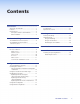
Contents Introduction............................................. 1 Reference Information........................... 31 About the TLP 350 MV..................................... 1 Features............................................................ 2 Requirements.................................................... 3 Computer Software and Hardware................ 3 Other Hardware............................................ 3 Included Parts.................................................
TLP 350MV • Contents vi
Introduction This guide describes the mounting, setup and operation of the TouchLink™ TLP 350MV panel. Unless otherwise stated, the terms “Touchpanel” “TouchLink Panel”, and “TLP 350” all refer to the TLP 350MV. About the TLP 350 MV The Extron TLP 350MV is a TouchLink Panel with a 3.5 inch screen that displays graphic objects and text.
The Extron GUI Configurator software, which is used to design the graphical user interface, allows the user to work with existing templates or create new interfaces on their PC. The completed project is uploaded to the TouchLink Panel. The Extron Global Configurator software is used to define the functions associated with the graphics created with GUI Configurator, providing versatility and adaptability to the configuration and control of an A/V system. Features 3.
Requirements Computer Software and Hardware The following system requirements are recommended for running GUI Configurator or Global Configurator 3.0: zz Operating System – Microsoft® Windows® XP SP2, Windows Vista®, or Windows 7 zz CPU – Intel® 1.2 GHz or compatible processor zz Memory – 1 GB of RAM zz Hard Disk space – 100 MB zz Microsoft .NET Framework 2.
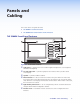
Panels and Cabling This section of the user guide describes: zz TLP 350MV Front Panel Features zz TLP 350MV Rear Panel Features and Connections TLP 350MV Front Panel Features 4 1 5 2 6 3 Figure 2. Front Panels Features a Light sensor — monitors the level of ambient light and adjusts the screen brightness and button backlighting. b 3.5 inch LCD screen — provides a graphical user interface with a pressable touch screen display. c d Speaker — provides audible feedback.
There are two recessed buttons and an LED behind the bezel. Use the Extron removal tool to remove the bezel. Remove bezel at tabs. Ex tro n Extron Removal Tool Figure 3. Use the Extron Removal Tool to Remove the Bezel These buttons are used for configuration of the unit and resetting parameters to factory defaults: 7 8 9 Figure 4. Front Panel Recessed Features g Menu button — recessed behind the bezel. It activates the on-screen menus for calibrating the unit.
TLP 350MV Rear Panel Features and Connections 11 10 12 Figure 5. j Rear Panel Features Network connector — the TLP 350MV connects to an Ethernet LAN using a twisted pair cable, terminated with an RJ‑45 connector (see the figure at right). Extron recommends using a Power over Ethernet (PoE) power supply. Use a straight-through Ethernet cable to connect the power supply to a switch or router. This cable carries network information from the switch or router to the power supply input.
An Extron IP Link control interface must also be connected to the same network domain. Available models are listed on page 3. The LAN Port connector (see the figure at right) has two LED lights. The Link LED lights green to indicate a good network connection. The Activity LED blinks yellow when network activity occurs.
Initial Configuration On-Screen Menus This section provides information about the on-screen menus that are used in the initial configuration and calibration of the TLP 350MV. The menus are factory-installed and cannot be altered by the user. When power is initially applied to the TouchLink Panel, the unit boots up and displays the opening screen. To access the on-screen menus, press the Menu button, which located below the screen, behind the bezel (g in figure 4).
Auto Backlight — automatically provides a suitable amount of backlighting calculated from the amount of ambient light detected by the light detector. Use the button to toggle between Off and On. When Auto Backlight is set to Off, Backlight allows the backlighting to be set manually from 0 to 100%. Use the volume control knob or press the Dn or Up buttons. The current value is shown above the buttons.
Time Screen Month: 08 Dn Up Day: 03 Dn Up Hours: 17 Dn Up Minutes: 30 Dn Up Year: 2010 Dn Up Main Figure 10. Time Screen Use the Dn (down) and Up buttons or the volume control knob to adjust the Month, Day, Year, Hours, and Minutes. NOTE: The Hours value uses the 24 hour clock. For 10 am, set Hours to 10; for 10 pm, set Hours to 22. After adjusting the Time screen, return to the Main screen to calibrate the next set of options.
Video Screen Contrast: 063 Dn Up Color: 064 Dn Bright: 127 Dn Up Up Tint: 129 Dn Up Main Figure 12. Video Screen Use the Dn (down) and Up buttons or the volume control knob to adjust: zz Contrast between 0 and 127 (default, 64) zz Color between 0 and 127 (default, 64) zz Brightness between 0 and 255 (default, 128) zz Tint between 0 and 255 (default, 128) The small rectangle provides a preview of incoming video and allows the user to adjust the video properties.
Configuration Software This section of the user guide provides information about: zz The Configuration Software zz Installing the Software zz Using the TouchLink Panel web Pages zz Updating the Firmware zz Using GUI Configurator zz Using Global Configurator The Configuration Software Designing a graphical user interface (GUI) for the TouchLink Panel takes two steps: 1. Design the layout of the text and graphics using GUI Configurator 2.
If required, locate the Global Configurator program on the disc or web site and install that also. By default, the Installer program creates and places the Global Configurator program in the C:\Program Files\Extron\GCx.x folder, where x.x represents the version of the Global Configurator program. During installation, there is an option to place an icon on the Windows desktop. Both programs can be downloaded from the Extron web site (www.extron.com).
2. Click on the Configuration tab and select the System Settings page, which allows the user to modify information about the IP settings and the date and time settings. These correspond to the IP settings (see page 10) and Time settings (see page 10) in the on‑screen menus. Figure 15. System Settings 3. Selecting Passwords allows the user to set passwords for an Administrator and a User. To set a password, follow the instructions at the top of the page. Figure 16. Passwords 4.
5. Click on the Touchpanel tab, which allows the user to alter the touchpanel and volume settings. These correspond to the Main settings (see page 8) and Volume settings (see page 9) in the on-screen menus. Figure 17. Touchpanel Configuration Updating the Firmware Firmware for the TLP 350MV can be upgraded using the Extron Firmware Loader or using your web browser. Before starting, consult your IT team and ensure that the TLP 350MV has a unique IP address.
3. From the same site, download the firmware for the TouchLink Panel unit. Click on the Download tab on the Extron home page and select the Firmware option. Figure 18. Extron Web Page — Download Center 4. Navigate to the TLP 350MV firmware and click Download. 5. This downloads the firmware to your computer. Make a note of the folder in which the firmware file is saved. 6. Open the Extron Firmware Loader by clicking on the desktop icon. 7. Select TLP 350MV from the Device drop-down menu. 8.
Updating Firmware From a Web Browser 1. Power on a computer that is connected to the same network as the TLP 350MV. 2. From the Extron web site (www.extron.com), download the firmware for the TLP 350MV. Click on the Download tab on the Extron home page and select the Firmware option (see figure 18). 3. Navigate to the TLP 350MV firmware and click Download. 4. This downloads the firmware to your computer. Make a note of the folder where the firmware file is saved. 5.
Using GUI Configurator This section provides an overview of the GUI Configurator program. For complete information about the program, consult the GUI Configurator help file (select Contents in the Help menu or press the key while within the program). NOTE: To configure the TLP 350MV, use GUI Configurator version 1.1 or later. To use the GUI Configurator program, follow these instructions: 1. Click on the desktop icon.
2. You can chose to: zz Start a New Project — Clicking OK opens a dialog box that offers a choice of project options. Figure 23. GUI Configurator New Project Dialog Box A series of icons offer you the choice of creating a project with a template or without a template and allow you to select the size and type of Touchlink Panel. If you are creating a project from an existing template, you can use the factory-loaded templates or you can select a template that you have previously created.
zz Download an Existing Project from a Panel — Clicking OK opens a dialog box that allows you to download a file that has been uploaded to a panel. Figure 25. GUI Configurator Download Project Dialog Box In the dialog box that opens, enter the IP address of the panel and use the Browse button to navigate to a folder where the file will be saved. Check Open the project and, Close Download Manager. Click on OK. The project is downloaded to your computer and opens in GUI Configurator.
3. Depending on which option was selected in step 2, GUI Configurator opens to a new or existing project. The initial screen is divided into a series of panes offering a range of tools that can be used to design or modify the project. For full details on how to use these tools, consult the help file (in the Help menu click on Contents or press the key while within the program). Figure 26. GUI Configurator Main Screen 4. To save the project, select Save Project from the File menu.
b. The Panel Manager dialog box opens: Figure 28. Add a TouchLink Panel (b) c. Click on the Add Panel icon to add a new panel to the list in the left pane. d. Highlight the name of the panel in the left pane to display the properties of that panel in the right pane. e. When a new panel is added, it is assigned the default IP address (192.168.254.254). To change the IP address, highlight the address property in the right pane and type in the correct IP address. Update any other properties, as required. f.
Using Global Configurator NOTE: To configure the TLP 350MV, use Global Configurator version 3.0.4 or later. This section provides an overview of the Global Configurator program. For complete information about the program, consult the Global Configurator help file (click on Contents in the Help menu or press the key while within the program). This section describes how to set up Global Configurator project with an IPL 250.
2. Select Create A New Project and click OK. The dialog box closes, leaving the Project Settings screen. Figure 30. Global Configurator Project Settings 3. Enter the IP Address for the TLP 350MV panel. The default Telnet connection is port 23 and HTTP is port 80, so these values do not usually need to be changed. If necessary, set administrator and user passwords. If required, set the date and time. Checking the Set Device as GlobalViewer Host box is optional.
4. Click OK and the Project Settings screen closes and is replaced by the Add Device dialog box: Figure 31. Global Configurator Add Device Dialog Box To see all the options, click on the Advanced >>> button. The button name changes to Basic <<< (as shown in the figure above). a. Select the IP Link device from the drop-down menu. In figure 32, above, an IPL 250 controller is added. Adding a different IP Link product is similar. b. Enter the IP address of the IP Link controller. The default value is 192.168.
5. Click OK and the Add Device screen closes. The start-up screen, which was behind it, is now visible, showing the IPL 250 and the available ports: Figure 32. Configuring an IP Link Device 6. Select TouchPanel Port 1. The screen shows the available options for the TouchLink Panel. To add the GUI Configurator project that was uploaded to the TouchLink Panel, click Click here to add one. Figure 33.
7. The Add TouchPanel dialog box opens. Figure 34. Add TouchPanel Dialog Box a. Ensure the TouchLink Panel model is selected from the drop-down menu and enter the IP address. b. Set the Telnet Port (usually 23) and, if necessary, enter the password. c. Check the Import/Apply Layout box and click OK. 8. The window now shows the GUI from the TouchLink Panel. Figure 35. Touchpanel GUI Loaded Onto Global Configurator 3 9.
Specifications TLP 350MV Display Screen type ������������������������������������ Size ������������������������������������������������ Resolution �������������������������������������� Dot/pixel pitch �������������������������������� Aspect ratio ������������������������������������ Color depth ������������������������������������ Transparency ���������������������������������� Brightness �������������������������������������� Contrast ����������������������������������������� Backlight ������������������
Audio output Speaker output ������������������������������ 1 mono, 89 dB SPL, 0.1 watt, 0.1 m, half space Frequency response ������������������������ 900 Hz to 6 kHz, ±5 dB Playback format(s) �������������������������� WAV files: 8 bit PCM, mono, 8 kHz sampling General Power �������������������������������������������� Supplied by an included power over Ethernet (PoE) adapter or an optional external 12 VDC, 1 A power supply Power input requirements �������������� +12 VDC, 0.
Product weight ������������������������������� Shipping weight ����������������������������� Vibration ���������������������������������������� Regulatory compliance Safety �������������������������������������� EMI/EMC ��������������������������������� Environmental �������������������������� MTBF ��������������������������������������������� Warranty ���������������������������������������� 1.0 lb (0.
Reference Information This section provides information about: zz Included Parts zz Optional Accessories Included Parts Description Part Number TLP 350MV 60-1077-0x Power over Ethernet power supply 28-156-0XLF 3-gang mud ring 70-581-32 Wall plate adapter (6) mounting screws Button kit (1) Extron removal tool DVD with software and user guide TLP 350MV • Setup Guide Optional Accessories Description Part Number Individual Buttons (see www.extron.
Mounting This section describes the procedures for mounting the TLP 350MV, including: zz Desktop Mounting zz Wall Mounting Desktop Mounting The TLP 350MV can be mounted in a desktop or table, using the optional SMB-303 surface mount box (part number ) or the SMB-303 with the SMA-1 swivel mount adapter (part number ). Follow the instructions provided with the mounting box and the adapter.
Using a Junction Box 1. Locate a wall stud and mark the position where the junction box will be placed. Use the specifications provided by the manufacturer. If necessary, cut a small hole in the wall immediately adjacent to the stud so that the position of the junction box can be marked precisely. Wall Stud Wall Box 2. Cut a hole in the wall. To avoid making the hole too big, cut inside the lines you marked in step 1. 3. Test the fit by inserting the junction box into the hole in the wall.
Mounting the TLP 350MV 1. Use the Extron removal tool to remove the bezel from the TLP 350MV (see page 5). Extron recommends using a Power over Ethernet (PoE) power supply. Connect a network switch to the “LAN-In” port of the power supply. Run a second network cable from the “Power + LAN-Out” port to the TLP 350MV. Leave enough slack in the cable to connect it to the back of the TLP 350MV. 2. Run video cables, with two BNC connectors, to the TLP 350MV.
5. If mounting to a wall box, insert the TLP 350MV into the wall adapter plate. Two clips at the top and two clips at the bottom audibly click as the panel moves into place. You should also secure the unit using the two screws provided (one top center, the other bottom center). Clips (4) Screws (2) Figure 38. Inserting the TLP 350MV into a Wall Box with a Wall Adapter Plate If you are mounting the unit to a mud ring, insert the TLP 350MV directly into the mud ring.
Reset Modes Occasionally, system conflicts make it necessary to reset firmware or IP settings. Extron IP Link controllers have five reset modes, four of which are available for the TLP 350MV. There is no mode 2 so that the numbering is consistent with the IP Link controllers.
TLP 350MV Reset Mode Summary Mode Activation Run/Stop Events Use Factory Firmware 1 Purpose/Notes The TLP 350 reverts to the factory default firmware. Event scripting does not start if the TLP 350 is powered on in this mode. All user files and settings (drivers, adjustments, IP settings, etc.) are maintained. NOTE: If you do not want to update firmware, or you performed a mode 1 reset by mistake, cycle power to the TLP 350 to return to the firmware version that was running prior to the mode 1 reset.
Button Kits Installing or Replacing Buttons A default set of eight front panel buttons are installed on the TLP 350MV. Any or all of these buttons can be replaced if they are assigned different functions when the unit is customized. Replacement buttons come in pre-packaged kits or can be ordered individually. See the Extron web site (www.extron.com) for a complete list of available options. An order form can be downloaded from the same site.
4. Remove the buttons that are being replaced. 5. Replace the buttons, as required, making sure that they are in the correct orientation. 4 Remove Buttons Figure 41. Remove and Replace the Buttons 6. Replace the bezel that was removed in step 2. Four clips, two at the top and two at the bottom, snap into place, audibly. Clips (4) DIS LA PT OP DV AU TE N FF Replacement Buttons D CC X YO PLA YO PLA MU PC DO DIS AM RY ILIA Figure 42. Replace the Bezel 7.
TLP 350MV • Button Kits 40
Extron Warranty Extron® Electronics warrants this product against defects in materials and workmanship for a period of three years from the date of purchase; touchscreen display and overlay components are covered for 1 year.
Installation Checklist Installation of the TLP 350MV can be divided into five main sections: Step 1 — Mount the TouchLink panel (select one option): Wall mount the TLP 350MV (page 32). Mount the TLP 350MV on a desk-top (page 32). If required, replace the buttons on the front panel (see page 38). Step 2 — Connect the power, network, and video cables, (select one option): Cable the TLP 350MV (page 6).