TPS150 Twisted Pair A/V Switching and Transmission System 68-958-01 Rev.
Precautions Safety Instructions • English Warning This symbol is intended to alert the user of important operating and maintenance (servicing) instructions in the literature provided with the equipment. Power sources • This equipment should be operated only from the power source indicated on the product. This equipment is intended to be used with a main power system with a grounded (neutral) conductor. The third (grounding) pin is a safety feature, do not a empt to bypass or disable it.
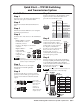
Quick Start — TPS150 Switching and Transmission System Installation Step 7 Step 1 Connect a host device to the transmitter via this 9-pin D connector and a null modem serial port cable for serial RS-232 control. Turn off power to the input and output devices, and remove the power cords from them. Step 2 If desired, mount the TPT150 transmitter in a rack. 5 Step 3 1 9 6 Female If desired, mount the TPR150 receiver using the included projector bracket.
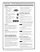
Quick Start — TPS150 Switching and Transmission System Step 10 See chapter 4, “Serial Communications”, to: Connect a projector or plasma display to the receiver’s video outputs. • Program a serial command to each of the transmitter’s Input Select buttons. Output 1 — Connect a VGA cable between the 15-pin HD female connector and the VGA or RGB input on the display. • Program projector power on and power off commands to the Projector Power button.
Table of Contents Chapter 1 • Introduction ....................................................................................................... 1-1 About this Manual ............................................................................................................. 1-2 About the Transmission System .................................................................................. 1-2 About the TPT150 switching transmitter .........................................................................
Table of Contents, cont’d Chapter 4 • Serial Communications ............................................................................... 4-1 ICS100 Windows-Based Control Program ............................................................... 4-2 System requirements ......................................................................................................... 4-2 Installing the software ......................................................................................................
TPS150 Switching and Transmission System 1 Chapter One Introduction About this Manual About the Transmission System TP Cable Advantages Features
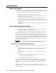
Introduction, cont’d Introduction About this Manual This manual contains installation, configuration, and operating information for the Extron TPS150 audio/video Twisted Pair (TP) switching and transmission system. • Chapter 1 identifies the transmitter’s and receiver’s features. • Chapter 2 details how to install the transmitter and receiver. • Chapter 3 describes how to operate the transmitter and receiver from their front panels and use all of their features.
The audio for the selected input is output locally. It is not sent to the receiver. The TPT150 has an RS-232 port that accepts ICS100 program control from a connected computer or serial command control from a computer or control system. The transmitter can also store serial commands that are entered by the operator. The transmitter sends the appropriate serial commands on the TP link to the receiver whenever an input button or the projector power button is pressed.
Introduction, cont’d TP Cable Advantages Twisted pair cable is much smaller, lighter, more flexible, and less expensive than coaxial cable. The TPT150 makes cable runs simpler and less cumbersome. Termination of the cable with RJ-45 connectors is simple, quick, and economical. Transmission distance The maximum distance is determined by the output frequency and resolution.
Audio output volume adjustment and muting — The output has volume control adjustment via the front panel, RS-232 control, or optional contact closure panel control. Control — Switcher control is available through the front panel, an RS-232 port serial link, and an optional contact closure control panel. Serial control is provided with the Extron ICS 100 control software and/or a control system issuing serial commands.
Introduction, cont’d 1-6 TPS150 Switching and Transmission System • Introduction
TPS150 Switching and Transmission System 2 Chapter Two Installation Mounting the Transmitter and Receiver Cabling and Rear Panel Views TP Cable Termination
Installation, cont’d Installation Mounting the Transmitter and Receiver The TPS150 comes with rubber feet for the transmitter and receiver, a set of MTR102 rack ears for the transmitter, and a set of mounting brackets for the receiver. Rack mounting the transmitter UL requirements The following Underwriters Laboratories (UL) requirements pertain to the installation of the transmitter into a rack (figure 2-1). 1.
3. Insert the transmitter into the rack, aligning the holes in the mounting bracket with those of the rack. 4. Secure the transmitter to the rack using the supplied machine screws. Projector mounting the receiver If desired, projector mount the receiver as follows: 1. Remove the rubber feet from the bottom of the receiver. 2. Attach the supplied 992547-2 projector pole mounting bracket to the receiver with the four provided #8 machine screws. 3.
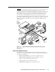
Installation, cont’d Cabling and Rear Panel Views Transmitter connections All connectors are on the rear panel (figure 2-3). INPUT 1 INPUT 2 AUDIO RGB / VGA INPUT 3 AUDIO L LOCAL MONITOR OUTPUT INPUT 4 R-Y VIDEO AUDIO L AUDIO PROJ PWR AUDIO UTP LINK VOL DN + R R Y B-Y R VOL UP IN4 R R Y 100–240 V .
TP and audio output connections 5 Output UTP Link connector — Connect one end of a TP cable to this RJ-45 female connector on the transmitter. Connect the free end of the same TP cable from the transmitter to the RJ-45 female connector on the receiver. See TP cable termination, on page 2-8, to properly wire the RJ-45 connector. The TPS150 works with either shielded or unshielded cables. However, to comply with FCC rules, shielded (STP or FTP) cables must be used.
Installation, cont’d 8 RS-232 port — Connect a host device, such as a computer or touch panel control, to the TPT150 transmitter via this 9-pin D connector and a null modem serial port cable for serial RS-232 control (figure 2-6).
Video output connections 12 RGB/VGA video connector — Connect a VGA cable between this 15-pin HD female connector and the VGA or RGB input on the display. 13 Composite video connector — Connect a video cable between this BNC female connector and the composite video input on the display. 14 S-video connector — Connect an S-video cable between this 4-pin mini DIN female connector and the S-video input on the display.
Installation, cont’d TP Cable Termination RJ-45 termination must comply with the TIA/EIA T 568A or TIA/EIA T 568B wiring standards for all connections. The TPS150 works with either shielded or unshielded cables. However, to comply with FCC rules, shielded (STP or FTP) cables must be used. Figure 2-8 details the recommended termination of CAT 5/5e/6 TP cable with RJ-45 connectors in accordance with the TIA/EIA T 568A or TIA/EIA T 568B wiring standards.
TPS150 Switching and Transmission System 3 Chapter Three Operation Controls and Indicators Operations Optimizing the Video Troubleshooting
Operation, cont’d Operation Controls and Indicators Transmitter controls and indicators The TPT150 transmitter will not operate properly unless it is connected to a powered TPR150 receiver. All of the transmitter’s controls are on the front panel (figure 3-1).
5 Volume up and down buttons — The Volume up ( ) and Volume down ( ) buttons are used to increase and decrease the output volume and the selected input’s audio level. See “Volume adjustment” on page 3-5 for more details. The Volume buttons are also used to reset the transmitter. See “Full system reset” on page 3-5. 6 Mute button and LED — Press the Mute button to toggle audio mute on and off. When the output is muted, the transmitter outputs no audio on its local Audio connector.
Operation, cont’d Operations The following paragraphs detail the power-up process and then describe selecting an input, issuing the projector power up and down commands, and adjusting the input level and output volume. Power Apply power to the transmitter by connecting the power cord to an AC source and toggling the AC power switch to the on ( ) position. Apply power to the receiver by connecting the power cord to an AC source.
Press the Projector Power button on the transmitter to issue the projector on or off command. When you push the button, the following occurs: • If no command has been transmitted since transmitter power was applied, or if the power off command was the last command transmitted: The transmitter sends the power on string to the receiver on the TP link. The transmitter lights its Projector Power LED. The transmitter starts its power off timout function (if enabled).
Operation, cont’d Optimizing the Video The TPR150 receiver features cable equalization controls for high and low frequency adjustments and RGB skew control to compensate for misconvergence of colors that can result from long CAT 5 cable runs. The following steps detail how to use these features to optimize the output image. These adjustments should be made with the highest resolution input selected on the TPT150 transmitter. 1.
Troubleshooting This section gives recommendations on what to do if you have problems operating the transmitter/receiver system, and it provides examples and descriptions for some image problems you may encounter. The following tips may help you in troubleshooting. • Some symptoms may resemble others, so you may want to look through all of the examples before attempting to solve the problem. • Be prepared to backtrack in case the action taken does not solve the problem.
Operation, cont’d Specific problems The table below shows some common operating problems and their solutions. Problem Possible cause No image appears. System is not receiving Ensure that the video source, the power. transmitter and receiver, and the display are plugged into a live AC power source and the transmitter is turned on. No video input Check that the input device is sending a video signal to the transmitter. No video output Select a different input.
TPS150 Switching and Transmission System 4 Chapter Four Serial Communications ICS100 Windows-Based Control Program Serial Commands
Serial Communications, cont’d Serial Communications The transmitter must be programmed with commands to be sent upon input selection and with projector power on/off commands before those commands are sent. The transmitter can also be configured with several serial port variables to match the controlling device and the device to be controlled. You can program and operate the transmitter either by using the ICS100 Windowsbased control program or by sending individual ASCII commands.
Establishing communications with the program The TPT150 transmitter will not operate properly unless it is connected to a powered TPR150 receiver. Start the control program and establish communications with the TPT150 as follows: 1. Click Start > Programs > Extron > ICS100. The control program window appears. The TPS150 does not respond until it has been contacted with the valid address.
Serial Communications, cont’d The transmitter’s serial port is factory-configured to 9600 baud, no parity, no flow control, half-duplex mode. If desired, the computer’s serial port settings can be changed from within the ICS100 program. 2. Click Communications > Comm Port > Comm 1 (or the correct Comm port). The Serial Port setup window appears (figure 4-3). Figure 4-3 — Serial Port setup window 3.
9. Click Inline Model > Query Hardware to configure the ICS100 program to communicate with the TPT150 and to confirm that communications have been established with the transmitter. The connected window appears (figure 4-5). Figure 4-5 — Connected window 10. Click OK. 11. Use the software to configure serial port settings, program the input and projector codes, and/or operate the transmission system. See the procedures on the following pages.
Serial Communications, cont’d Using the software to configure the serial port settings If necessary, use the ICS 100 software to change the serial port settings of either the transmitter or receiver. The transmitter’s serial port is factory-configured to 9600 baud, no parity, no flow control, half-duplex mode. If desired, serial port settings can be changed from within the ICS100 program. 1. Click Communications > Comm Port > Comm 1 (or the correct Comm port).
Using the software to program the input and projector codes Use the control program to program the transmitter’s input selection and projector power on/off buttons as follows: 1. Click Controls > Projector Codes > Input Codes. The Program Projector Codes window appears (figure 4-7). Figure 4-7 — Program Projector Codes window 2. For each input or projector code to be programmed: a.
Serial Communications, cont’d c. Enter the desired code in the code window (figure 4-9). Spaces are ok when you are entering ASCII codes. Figure 4-9 — Code entry (ASCII code) Codes that are intended to be hex codes must be in pairs (such as 03 or DE). Use a leading 0 if necessary. Letters must be uppercase. Spaces between bytes are acceptable in ASCII codes (figure 4-9), but are not allowed in hex codes (figure 4-10).
3. Repeat step 2 for each button or code to be programmed. 4. Click 5. Click Controls > Projector Codes > Projector Delay. The Program Projector Delay window appears (figure 4-13). in the upper right corner of the window to close the window. Figure 4-13 — Program Projector Delay window When you open the window, the ICS 100 automatically resets the projector delay in the transmitter to 0 seconds and displays 000 in the variable window. 6.
Serial Communications, cont’d With the exception of input audio level, the controls on the control panel window operate the same as the physical front panel of the transmitter. See chapter 3, Operation. 2. If you click the Projector On or Projector Off button, the Projector Power LED on the transmitter’s front panel blinks while the delay times out. All front panel operations are disabled during the delay. The button mutes and unmutes the audio output.
Serial Commands Communication protocols The transmitter’s and receiver’s serial ports (figure 4-16) are factory-configured to 9600 baud, no parity, no flow control, half-duplex mode. If you change the transmitter’s serial protocols, communications between the computer and the transmitter are lost until the computer is updated to match the new transmitter settings.
Serial Communications, cont’d When the system is in Pass-Through mode [CC98], commands and responses are sent between the transmitter and receiver. If the system is not in Pass-Through mode, all of the receiver responses to the transmitter’s button commands are buffered until you return the system to mode, at which time the buffered responses are sent back to the controlling device. In this way, the controller can track the activity that has occurred.
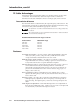
X2 = Input number 01 – 04 X3 = On/off status 0 = off, 1 = on X4 = Input volume –15 (dB) of attenuation (minimum volume) through 00 (dB) (maximum volume) X5 = Output level –31 (dB) of attenuation (maximum attenuation) through 20 (dB) (maximum gain) X6 = Button or code 01 = input 1 code 02 = input 2 code 03 = input 3 code X7 = ASCII button code Up to 63 alphanumeric characters.
Serial Communications, cont’d Command/response table for programming and operating the TPT150 Command ASCII Command Response (host to TPT150) (TPT150 to host) Connect [CC X1 ] {none} Change address number [ADDR X1 ] [R0• X1 •ADDR X1 •] [ADDR95] [R0•95•ADDR95•] [ADDR@] [R0• X1 •ADDR@•] Select an input [CH X2 ] [R0• X1 •CH X2 •] Increment input selection [CH+] [R0• X1 •CH+•] Decrement input selection [CH–] [R0• X1 •CH–•] Query input selection [CH?] [R0• X1 •CH?• X2 ] Blank the output
Command/response table for programming and operating the TPT150 (Cont’d) Command ASCII Command Response Additional description (host to switcher) (switcher to host) [VIN X2 [R0• X1 •VIN X2 Input audio level Adjust the input audio level X4 0] X4 0•] Set the input X2 audio level to a specified value. Leading zeros are required in the input number ( X2 ). Two-digit numbers are required for the audio level variable ( X4 ); use leading zeroes as required.
Serial Communications, cont’d Command/response table for programming and operating the TPT150 (Cont’d) Command ASCII Command Response (host to switcher) Additional description (switcher to host) Program projector power and input command codes (continued) Reset button code (ASCII or hex) [PCL1 X6 @] [R0• X1 •PCL1 X6 @•] Assign a projector power timeout [TOUT05 X9 ] [R0• X1 •TOUT05 X9 •] [TOUT05060] [R0•97•TOUT05060•] [TOUT05?] [R0• X1 •TOUT05?• X9 ] Send projector power code [PPWR X3 ] [R0• X
Command/response table for programming and operating the TPT150 (Cont’d) Command ASCII Command Response (host to switcher) (switcher to host) Disable front panel Enable front panel (default) Toggle front panel lockout [FP0] [FP1] [FP] [R0• X1 •FP0•] [R0• X1 •FP1•] [R0• X1 •FP•] View front panel lockout [FP?] [R0• X1 •FP?• X3 ] [DFLT X16 ] {none} [ARC] [R0• X1 •ARC• X17 Additional description Front panel lockout Disable the transmitter’s buttons. Enable transmitter’s buttons.
Serial Communications, cont’d 4-18 TPS150 Switching and Transmission System • Serial Communications
TPS150 Switching and Transmission System A Appendix A Reference Information Specifications Part Numbers
Reference Information Specifications Video Gain ................................................ Crosstalk ....................................... Number/signal type ................... Connectors ................................... Unity -42 dB @ 10 MHz 1 set of proprietary analog signals 1 RJ-45 female jack Video input Number/signal type TPT150 ...............................
Sync Input type ..................................... Output type .................................. Standards ...................................... Input level ..................................... Output level .................................. Input impedance .......................... Output impedance ....................... Max. input voltage ....................... Max. propagation delay .............. Max. rise/fall time ....................... Polarity ..........................................
Reference Information, cont’d Program control .......................... Inline Control Software for Windows® – lCS100 Control — projector (TPR only) Projector control port ................. RS-232, 9-pin male D connector Baud rate and protocol ............... 38400, 19200, 9600 (default), 4800, 2400, or 1200 baud (configurable); 8 data bits; 1 (default) or 2 stop bits; no parity (default), or even or odd parity General Power ............................................
Part Numbers Included parts These items are included in each order for a TPS150: Included parts TPS150 twisted pair (TP) switching and transmission system TPT150 switching transmitter TPR150 receiver Rack mounting ears Projector pole mounting brackets 3.81 mm captive screw connector 3.5 mm captive screw connector ICS100 control software IEC power cord Tweeker (small screwdriver) TPS150 User’s Manual VGA M6' MHR (molded) VGA cable (6 feet/1.83 meters) 6' component video cable (6 feet/1.
Reference Information, cont’d A-6 TPS150 Switching and Transmission System • Reference Information
FCC Class A Notice Note: This equipment has been tested and found to comply with the limits for a Class A digital device, pursuant to part 15 of the FCC Rules. These limits are designed to provide reasonable protection against harmful interference when the equipment is operated in a commercial environment. This equipment generates, uses and can radiate radio frequency energy and, if not installed and used in accordance with the instruction manual, may cause harmful interference to radio communications.
www.extron.com Extron Electronics, USA Extron Electronics, Europe Extron Electronics, Asia Extron Electronics, Japan 1230 South Lewis Street Anaheim, CA 92805 USA 714.491.1500 Fax 714.491.1517 Beeldschermweg 6C 3821 AH Amersfoort The Netherlands +31.33.453.4040 Fax +31.33.453.4050 135 Joo Seng Road, #04-01 PM Industrial Building Singapore 368363 +65.6383.4400 Fax +65.6383.4664 Kyodo Building 16 Ichibancho Chiyoda-ku, Tokyo 102-0082 Japan +81.3.3511.7655 Fax +81.3.3511.