
User guide
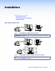

Ä Transmitter output connector — A female RJ-45 connector on a 3 inch pigtail for the
VTT001 MAAP, or within the VTT001 model. Plug the twisted pair cable going to the
receiver into this connector.
CAUTION: Do not connect the transmitter to a computer data or
telecommunications network.
Å Receiver input connector — A female RJ-45 connector on a 3 inch pigtail for the
VTR001 MAAP and VTR001 AAP models, or within the VTR001 model. Plug the twisted
pair cable coming from the transmitter into this connector.
CAUTION: Do not connect the receiver to a computer data or telecommunications
network.
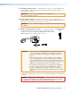
Ç Captive screw input power connector — Connect the included
12 VDC external power supply to the 2-pole female direct insertion
captive screw connector. The VTT001 MAAP, VTR001 AAP, and the
VTR001 MAAP have this captive screw connector.
9VDC-12VDC
500mA
TX
Power Supply
Output cord
AA
SECTION A–A
CAUTIONS: • AlwaysuseapowersupplysuppliedbyorspecifiedbyExtron.Use
of an unauthorized power supply voids all regulatory compliance
certification and may cause damage to the supply and the end
product.
• Unlessotherwisestated,theAC/DCadaptersarenotsuitablefor
use in air handling spaces or in wall cavities. The power supply is
to be located within the same vicinity as the Extron AV processing
equipment in an ordinary location, Pollution Degree 2, secured to the
equipment rack within the dedicated closet, podium or desk.
• Theinstallationmustalwaysbeinaccordancewiththeapplicable
provisions of National Electrical Code ANSI/NFPA 70, article 75
and the Canadian Electrical Code part 1, section 16. The power
supply shall not be permanently fixed to building structure or similar
structure.
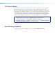
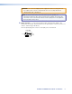
To verify correct polarity before connection, check the power supply no load output with
a voltmeter.
WARNING: May result in serious injury.
The two power supply leads must be kept separated while the power supply is
plugged into an electrical outlet. Remove power before wiring.
Power Connection
+
–
12VDC
Power
VTT001 and VTR001 User Guide • Installation 4