User’s Manual P/2 DA8 and P/2 DA12 Series VGA Distribution Amplifiers 68-1475-01 Rev.
Precautions Safety Instructions • English This symbol is intended to alert the user of important operating and maintenance (servicing) instructions in the literature provided with the equipment. This symbol is intended to alert the user of the presence of uninsulated dangerous voltage within the product’s enclosure that may present a risk of electric shock. Caution Read Instructions • Read and understand all safety and operating instructions before using the equipment.
安全须知 • 中文 警告 这个符号提示用户该设备用户手册中 有重要的操作和维护说明。 电源 • 该 设 备 只 能 使 用 产 品 上 标 明 的 电 源 。 设 备 必须使用有地线的供电系统供电。 第三条线 (地线)是安全设施,不能不用或跳过。 这个符号警告用户该设备机壳内有暴 拔掉电源 • 为安全地从设备拔掉电源,请拔掉所有设备后 或桌面电源的电源线,或任何接到市电系统的电源线。 露的危险电压,有触电危险。 电源线保护 • 妥善布线, 避免被踩踏,或重物挤压。 注意 阅读说明书 • 用 户 使 用 该 设 备 前 必 须 阅 读 并 理 解所有安全和使用说明。 保存说明书 • 用户应保存安全说明书以备将来使 用。 遵守警告 • 用户应遵守产品和用户指南上的所有安 全和操作说明。 维护 • 所有维修必须由认证的维修人员进行。 设备内部 没有用户可以更换的零件。为避免出现触电危险不要自 己试图打开设备盖子维修该设备。 通风孔 • 有些设备机壳上有通风槽或孔,它们是用来防止 机内敏感元件过热。 不要用任何东西挡住通风孔。 锂电池 • 不正确的更换电池会有爆炸的危险。 必须使用 与厂家推荐的相同
Table of Contents Chapter One • Introduction ..................................................... 1-1 About This Manual .................................................................... 1-2 Description of P/2 DA8 and P/2 DA12 Series .................... 1-2 Features of P/2 DA8 and P/2 DA12 Series .......................... 1-3 Chapter Two • Installation and Operation . .................. 2-1 Installation Overview . ..............................................................
Table of Contents, cont’d ii P/2 DA8 and P/2 DA12 • Table of Contents
P/2 DA8 and P/2 DA12 Series 1 Chapter One Introduction About this Manual Description of P/2 DA8 and P2 DA12 Series Features of P/2 DA8 and P2 DA12 Series
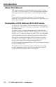
Introduction About This Manual This manual contains information about the Extron P/2 DA8, P/2 DA8 A, P/2 DA12 and P/2 DA12 A distribution amplifiers with instructions on how to mount, install, and operate these units. Unless otherwise specified, references to "the distribution amplifier" in this manual relate to the features or operation of all four of these models.
Features of P/2 DA8 and P/2 DA12 Series Bandwidth — 350 MHz (-3dB) RGB video bandwidth, fully loaded, which is compatible with resolutions from VGA to QXGA. Wide range of compatible signal types and resolutions — all models are able to accept and distribute RGBHV, RGBS, RGsB, RsGsBs, YUV (tri-level and bi-level sync), S-video and composite video signals. Power LED — located on front panel. It has a dual purpose as power indicator and input signal status.
Introduction, cont’d 1-4 P/2 DA8 and P/2 DA12 • Introduction
P/2 DA8 and P/2 DA12 Series 2 Chapter Two Installation and Operation Installation Overview Mounting the Distribution Amplifier Front Panel Features Rear Panel Features Operation Troubleshooting
Installation and Operation Installation Overview The distribution amplifiers can be mounted on tabletops, in racks and under furniture. Through-desk mounting is not recommended for these products. To install these units, follow these steps: 1. Turn off all electrical equipment. Make sure that the input sources, the distribution amplifier, and the output displays are all turned off, disconnected from their power sources, and connecting cables have been removed. 2.
overloading might have on overcurrent protection and supply wiring. Give appropriate consideration to the equipment nameplate ratings when addressing this concern. 5. Reliable earthing (grounding) — Maintain reliable grounding of rack-mounted equipment. Pay particular attention to supply connections other than direct connections to the branch circuit (such as the use of power strips).
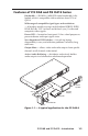
Installation and Operation, cont’d Under-desk mounting Mount the unit under a desk or podium using the optional Extron MBU 149 kit (part #70-222-01) as follows: 1. Remove rubber feet if these have been installed on the bottom of the unit. 2. Using the provided #8 screws, attach the mounting brackets to the distribution amplifier (four screws on each side, as shown below in figure 2). Mounting Screws (2 Plcs) Each Side #8 Screw (4 Plcs) Each Side Figure 2-2 — Under-desk mounting the interface 2-4 3.
P/2 DA8 and P/2 DA12 • Installation and Operation 2-5
Installation and Operation, cont’d Front Panel Features The front panels in the figure below show the P/2 DA8 series (upper panel) and P/2 DA12 (lower panel). SYNC IMPEDANCE 1 ON OFF 2 3 4 5 2 3 4 5 ON 1 P/2 DA8 Series DISTRIBUTION AMPLIFIER 1 2 SYNC IMPEDANCE 1 ON OFF 2 3 4 5 6 7 2 3 4 5 7 ON 1 6 P/2 DA12 Series DISTRIBUTION AMPLIFIER Figure 2-3 — Front panel features a b 2-6 Power LED — indicates power and input signal status.
Rear Panel Features All power, input and output connections are located on the rear panels of all models, as shown in the figure below. 100-240V 0.3A INPUT 1 3 2 4 VIDEO OUTPUTS 5 7 6 8 MUTE A 1 3 5 7 2 4 6 8 P/2 DA8 50/60 Hz 100-240V 0.3A INPUT 1 3 2 4 VIDEO OUTPUTS 5 7 6 8 MUTE AUDIO OUTPUTS L 1 R L 3 R L 5 R L 7 R A 1 3 5 7 L 2 R L 4 R L 6 R L 8 R 2 4 6 8 P/2 DA8 A 50/60 Hz 3 100-240V 4 6 5 0.
Installation and Operation, cont’d Operation After the distribution amplifier and its connected devices are powered up, the system is fully operational. If any problems occur, ensure that the cables are properly routed and connected. Sync impedance switches To solve laptop compatibility issues on the video input, or reflection problems on the video output, use these dip switches to correct for sync impedance mismatches.
Video Input and Output Connections All models are able to accept RGBHV, RGBS, RGsB, RsGsBs, YUV (tri-level and bi-level sync), S-video and composite video, and resolutions from VGA (640 x 480) to QXGA (2048 x 1536). The signal is distributed without modification: the output format follows the input format. To make input and output connections with other devices, follow these instructions: 1. Turn off the power to the distribution amplifier and the video source. 2.
Installation and Operation, cont’d Audio input For models P/2 DA8 A and P/2 DA12 A, use a female 3.5 mm mini Tip Ring Sleeve (TRS) connector to provide an unbalanced audio input. Switch off power to the distribution amplifier and audio source. Connect the audio source to the audio input socket on the rear Audio Input panel of the distribution amplifier. INPUT Wiring for the TRS connector is shown in the figure below. Tip (L) Ring (R) Sleeve ( ) Tip Left + Ring Right + Sleeve Ground 3.
R Right Unbalanced Stereo Output Tip Ring Sleeve(s) Tip Ring Left R Left L L Tip NO GROUND HERE. Sleeve(s) Tip NO GROUND HERE. Right Balanced Stereo Output CAUTION For unbalanced audio, connect the sleeve(s) to the center contact ground. DO NOT connect the sleeve(s) to the negative (-) contacts. Figure 2-8 — Audio output wiring Mute Control The mute control provides a way to mute individual outputs, or all outputs at once. Audio and video for each output is muted simultaneously.
Installation and Operation, cont’d Troubleshooting After input and display devices are connected to the distribution amplifier and all units are powered up, the system is fully operational. If any problems occur, ensure that the cables are properly routed and connected. Some common problems and diagnostic checks are shown below: If the LED light on the front panel is not on, the distribution amplifier is not receiving power.
P/2 DA8 and P/2 DA12 Series A Appendix A Reference Information Specifications Included Parts Accessories
Reference Information Specifications Video Gain.................................................. Unity Bandwidth....................................... 350 MHz (-3 dB) Video Input Number/signal type...................... 1 VGA-QXGA RGBHV, RGBS, RGsB, RsGsBs, HDTV component video, S-video, composite video Connectors...................................... (1) 15-pin HD female (optional Mac/VGA adapters are available) Nominal level................................. 1.
Sync Input type........................................ RGBHV, RGBS, RGsB, RsGsBs; bi-level and tri-level sync Output type..................................... RGBHV, RGBS, RGsB, RsGsBs; bi-level and tri-level sync (follows input) Tri-level on Y, R-Y, B-Y channels (component video 720p, 1080i, 1080p) Bi-level on Y channel (for all other component video rates) Input level....................................... 2.0 V to 5.0 Vp-p (TTL) Output level.................................... 0.
Reference Information, cont’d Audio — P/2 DA8 A, P/2 DA12 A Gain.................................................. Unbalanced output: 0 dB; Balanced output: + 6 dB Frequency response....................... 20 Hz to 20 kHz, ± 0.2 dB THD + Noise................................... 0.03% @ 1 kHz at nominal level S/N................................................... >90 dB at maximum output (unweighted) Stereo channel separation............. >80 dB @ 1Hz Audio Input — P/2 DA8 A, P/2 DA12 A Number/signal type..
Contact closure pin configurations P/2 DA8 series................... A = mute all outputs, 1 = mute output 1, 2 = mute output 2, 3 = mute output 3,... 8 = mute output 8 P/2 DA12 series................. A = mute all outputs, 1 = mute output 1, 2 = mute output 2, 3 = mute output 3,... 12 = mute output 12 General Power............................................... 100 VAC to 240 VAC, 50/60 Hz, 30 watts, internal Temperature/humidity.................
Reference Information, cont’d Included Parts Included Parts Part number P/2 DA8 60-891-02 or P/2 DA8 A 60-891-01 or P/2 DA12 60-893-02 or P/2 DA12 A 60-893-01 IEC Power Cord Tweeker Rubber Feet (4) 3.5 mm, 3-pole captive screw connector w/tail (blue) — Audio models only (2) 100-456-01 3.5 mm, 4-pole captive screw connector w/tail (blue) — Audio models only (2) 3.5 mm, 5-pole captive screw connector w/tail (blue) — Audio models only (8 for P/2 DA8; 12 for P/2 DA12) 100-457-01 Zip Tie, clear.
Accessories Part number SY VGAM-RGBHVF, VGA male to BNC female molded adapter, various lengths 26-397-01 SY VGAM-RGBHVF, VGA male to BNC female pig tail adapter, various lengths 26-604-02 MHR-5 BNC Series, BNC male to male 5 conductor MHR cables, various lengths 26-260-xx MHR-5P BNC Series, BNC male to male 5 conductor plenum MHR cables, various lengths 26-378-xx M59-5 BNC Series, BNC male to male 5 conductor M59 flex cables, various lengths 26-499-xx RG6-5 BNC Series, BNC male to male 5 conduct
Reference Information, cont’d A-8 P/2 DA8 and P/2 DA12 • Reference Information
FCC Class A Notice Note: This equipment has been tested and found to comply with the limits for a Class A digital device, pursuant to part 15 of the FCC Rules. These limits are designed to provide reasonable protection against harmful interference when the equipment is operated in a commercial environment. This equipment generates, uses and can radiate radio frequency energy and, if not installed and used in accordance with the instruction manual, may cause harmful interference to radio communications.
www.extron.com Extron Electronics, USA 1230 South Lewis Street Anaheim, CA 92805 800.633.9876 714.491.1500 FAX 714.491.1517 Extron Electronics, Europe Beeldschermweg 6C 3821 AH Amersfoort, The Netherlands +800.3987.6673 +31.33.453.4040 FAX +31.33.453.4050 Extron Electronics, Asia 135 Joo Seng Rd. #04-01 PM Industrial Bldg., Singapore 368363 +800.7339.8766 +65.6383.4400 FAX +65.6383.4664 © 2008 Extron Electronics. All rights reserved.