
User Guide Rev. D User Manual


VTG 300/300R • Quick Start Guide
CAUTION
Operation and service must be performed by authorized
personnel only. These units must be operated in
accordance with national and local electrical codes.
Prior to using the VTG 300R for the first time, please be
sure that the batteries are fully charged.
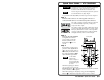
To operate the VTG 300/300R, follow these steps and see chapter 2.
Step 1
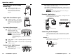
Connect a video device to one of the top panel connectors or
connect an audio device to one of the bottom panel connectors.
The video connectors located on the top panel will
accommodate RGB, component, S-video, and
composite video output.
The audio connectors located on the bottom panel
will accommodate unbalanced mono audio on the
RCA jack, balanced mono audio on the 3-pin XLR
connector, and unbalanced mono audio (both left
and right channels) on the 3.5 mm mini jack.
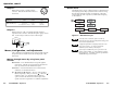
Step 2
Power up the VTG 300/300R.
Using either the external
power supply or internal
batteries, hold down the
Power button
7
for one
second.
Step 3
If generating an audio signal,
press the audio Signal button
2
to select an audio signal, as
indicated by the lit LED. Press
the audio Level buttons
3
to
adjust the RMS signal level.
See the Audio
Setup menu
section in chapter 2
to specify either dBu
or dBV as the signal
level unit.
When the signal type is either a
sine or square wave, press the
Frequency buttons
4
to adjust the frequency from 20 Hz to 20 kHz
(sine) or 20 Hz to 5 kHz (square).
When the signal type is frequency sweep, press the Frequency
buttons
4
to adjust the sweep interval from 1.5 sec to 150 sec.
Quick Start Guide — VTG 300/300R
QS-1
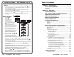
VTG 300
VIDEO TEST GENERATOR
SIGNAL
TEST
PATTERNS
RANGE
OUTPUT RATE
RATE
MENU
NEXT
POWER
SELECT
LEVEL
FREQUENCY
P.N O I S E
W. NOISE
SINE
SQUARE
POLARITY
SWEEP
X-HATCH
H PATTERN
COL. BARS
GRAYSCALE
ALT/ MULTI
WHT. FIELD
PC
VIDEO
HDTV
16:9 HR
AUDIO VIDEO
8
9
10
11
6
2
3
5
4
1
7
Front panel
RGB/Y,R-Y,R-Y S-VIDEO COMPOSITE
VIDEO
Top panel
AUDIO
3
2
1
Bottom panel