
User Guide Rev. D User Manual


VTG 300/300R • Operation
VTG 300/300R • Operation
Operation
2-3
4
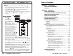
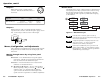
Audio frequency adjustment (Frequency) — When the audio
signal type is either a sine or square wave (see
2
above), the
audio frequency can be adjusted from 20 Hz to 20 kHz (sine) or
20 Hz to 5 kHz (square). Press the button to increase the
frequency and the
button to decrease the frequency. The
adjustment is in 1/3 octave steps. See Setting the Audio
Frequency in this chapter.
5
Menu selection (Menu) — Press the Menu button to advance
through the four main menus. See the Menus, Configuration, and
Adjustments section in this chapter.
6
Next — Press the Next button to step through the submenus.
See the Menus, Configuration, and Adjustments section in this
chapter.
7
Power — Power up or power down the VTG 300 by holding
down the Power button for one second.
If the Power button is held down for more than three
seconds, the VTG will automatically turn off. This
feature will prevent the VTG from being left on
unintentionally should the power button be
unknowingly pressed.
8
Video test patterns (Test Patterns) — Press this button to select
from among 13 different test patterns in six categories, as
indicated by green LEDs to the left of each category: crosshatch
(X-hatch), H pattern, color bars (Col. Bars), grayscale,
alternating pixels/multiburst (Alt./Multi), or white field (Wht.
Field). See Selecting a Video Test Pattern in this chapter.
9
Video output range (Range) — Select the video output signal
range, as indicated by green LEDs to the left: computer scan
rates (PC), video scan rates (Video), HDTV scan rates (HDTV),
or 16:9 HR scan rates.
10
Video output rate adjustment (Rate) — Press the button or
button to vary the scan rate for a selected output range.
11
Select video output rate (Select) — Select and activate the
desired output rate for a given range by pressing this button.
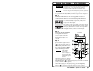
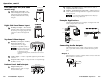
Front Panel Features
1
LCD — A two-
row liquid
crystal display
for viewing the
VTG status,
menus, and
options.
2
Audio signal
type (Signal) —
Press this button
to select from
among six
different audio
signals, as
indicated by
green LEDs to
the right: pink
noise (P. Noise),
white noise (W.
Noise), sine
wave (Sine),
square wave
(Square),
polarity test
(Polarity), and
swept sine wave
(Sweep).
3
Audio output
signal level
adjustment
(Level) — Press the button to increase the RMS signal level
and the button to decrease the RMS signal level. See the
Audio Setup menu section in this chapter to specify either dBu or
dBV as the signal level unit.
The audio output level settings for all audio signal types (see
2
above) are retained after the VTG is powered off. The default
setting is -28 dBu for polarity and -10 dBu for all other signal
types.
If the Level buttons are held down for more than one
second, the VTG will automatically increment the level
adjustment in the direction indicated by the button.
2-2
VTG 300
VIDEO TEST GENERATOR
SIGNAL
TEST
PATTERNS
RANGE
OUTPUT RATE
RATE
MENU
NEXT
POWER
SELECT
LEVEL
FREQUENCY
P.NOISE
W. NOISE
SINE
SQUARE
POLARITY
SWEEP
X-HATCH
H PATTERN
COL. BARS
GRAYSCALE
ALT/ MULTI
WHT. FIELD
PC
VIDEO
HDTV
16:9 HR
AUDIO VIDEO
8
9
10
11
6
2
3
5
4
1
7
Front panel