
User Guide Rev. E User Manual


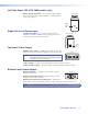

Left Side Panel LED (VTG 300R model only)
Battery charge status LED — The amber LED lights steadily
CHARGE
STATUS
Left side panel
Battery
charge
LED
when the VTG is being charged, and blinks steadily when the
VTG is fully charged.
Right Side Panel Power Input
12 VDC power input — The included external 12 VDC,
12 VDC 1A
Right side panel
12 VDC
Power
Input
100 VAC to 240 VAC, 50/60 Hz power supply plugs into this
connector located on the right side panel.
Top Panel Video Output
RGB/R-Y, Y, B-Y output — RGBHV, RGBS, RGsB, RsGsBs, and
component video are output through the 15-pin HD connector.
RGB/R-Y,Y,B-Y S-VIDEO COMPOSITE
VIDEO
Top panel
NOTE: For NTSC/PAL rates, the component video output is
intended for signal verification and alignment, and
should not be used as a reference.
S-video output — S-video is output through the 4-pin mini DIN connector.
Composite video output — Composite video is output through the BNC connector.
Bottom Panel Audio Output
Output 1: RCA jack — Unbalanced mono audio is output
AUDIO
3
2
1
Bottom panel
from this female jack.
Output 2: 3-pin XLR connector — Balanced mono audio
is output from this male connector.
Output 3: 3.5 mm mini stereo phone jack — Unbalanced
mono audio on both left and right channels is output from this female mini phone jack.
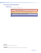
NOTE: See Connecting Audio Outputs for audio wiring instructions.
VTG 300/300R • Operation 4