
User Guide Rev. E User Manual


Operation
This section describes:
• Front Panel Features
• Left Side Panel LED (VTG 300R model only)
• Right Side Panel Power Input
• Top Panel Video Output
• Bottom Panel Audio Output
• Example Applications
• Connecting Audio Outputs
• Menus, Configuration, and Adjustments
• Additional Functions
• Audio Testing Features
• Video Testing Features
• Installing the VTG 300 Batteries
• Conserving the VTG 300 Battery Life
• Recharging the VTG 300R
• Installing the Protective Boot
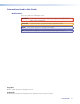
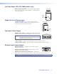
Front Panel Features
• LCD Display— A two-row liquid crystal
VTG 300R
VIDEO & AUDIO TEST GENERATOR
SIGNAL
TEST
PATTERNS
RANGE
OUTPUT RATE
RATE
MENU
NEXT
POWER
SELECT
LEVEL
FREQUENCY
P.NOISE
W. NOISE
SINE
SQUARE
POLARITY
SWEEP
X-HATCH
H PATTERN
COL. BARS
GRAYSCALE
ALT/ MULTI
WHT. FIELD
PC
VIDEO
HDTV
16:9 HR
AUDIO VIDEO
Signal
Button
Level
Buttons
Frequency
Buttons
Menu
Button
Next
Button
Power
Button
Test Patterns
Button
Range
Button
Rate
Button
Select
Button
LCD
Display
VTG 300R
Front panel
display for viewing the VTG status, menus,
and options.
Audio buttons (left side):
• Signal Button (audio signal type) —
Press this button to select from among six
different audio signals, as indicated by
green LEDs to the right:
• Pink noise
(P. Noise),
• White noise
(W. Noise)
• Sine wave
(Sine)
• Square wave
(Square)
• Polarity test
(Polarity)
• Swept sine
wave (Sweep)
• Level Buttons (audio output signal
level adjustment) — Press the button
to increase the RMS signal level and the
button to decrease the RMS signal level.
See the Audio Setup menu section to specify either dBu or dBV as the signal level unit.
2VTG 300/300R • Operation