Assembly Manual GATEWAY™ 3G Solid Surface Portable Ramp Available with or without handrail options Ramp Only Ramp w/ Two-line Handrails Ramp w/ Handrails and Vertical Pickets LIFETIME WARRANTY. Please register at www.ezaccess.com/warranty-satisfaction. © EZ-ACCESS®, a division of Homecare Products, Inc. All rights reserved.
ASSEMBLY MANUAL EZ-ACCESS® GATEWAY™ 3G Solid Surface Portable Ramp ATTENTION INSTALLER AND END USER • • • • Please leave this Assembly Manual with the end user. Read all instructions prior to ramp installation. For residential use ONLY; do not use in commercial applications. RATED LOAD: 1,000 pounds. NEVER EXCEED RATED LOAD. VIEW PACKING LIST • Each system is shipped with a packing list. Be sure to check that all items are present before starting assembly/installation.
1. BASIC SAFETY AND WARNINGS 1.1. 1.2. SYMBOL MEANINGS WARNING SYMBOL: This symbol may appear in various colors and in conjunction with other symbols. The WARNING symbol indicates that a failure to obey the warning could result in property damage, damage to equipment, serious personal injury, or death, as well as the serious personal injury or death of others. NOTE SYMBOL: This symbol may appear in various colors and in conjunction with other symbols.
2. AVAILABLE GATEWAY 3G RAMPS 2.1. The EZ-ACCESS® GATEWAY™ 3G Solid Surface Portable Ramp (also referred to as ‘GATEWAY 3G Ramp’ or ‘ramp’ throughout this manual) is available in 3’, 4’, 5’, 6’, 7’, 8’, 9’, and 10’ lengths. All ramps come with 1 self-adjusting lower transition plate, 1 fixed top lip transition plate, 4 side rail protective caps, and 2 clevis pins. The 3’-8’ ramp lengths come standard with 2” curbs; 9‘ and 10’ lengths come standard with 4” curbs. 2.2. GATEWAY 3G Ramp Only (FIG.
3. FASTENING RAMP TO LANDING (ALL RAMPS) 3.1. 3.2. 3.3. 3.4. The ramp’s top lip transition plate must be properly fastened to the landing before use. Consult a contractor for additional information. If your ramp includes handrails, it is necessary to install the end brackets on the ramp before fastening the ramp to the landing (refer to SECTION 4). Place the ramp’s top lip transition plate (identifiable by the two pre-drilled holes) so it extends onto the landing as far as possible.
4. INSTALLING (OPTIONAL) HANDRAILS If ramp does not include optional handrails, skip to SECTION 6. 4.1. Both handrail styles – two-line and handrails with vertical pickets – come pre-assembled. Regardless of the style, the process of attaching handrails to the ramp is the same. 4.2. Turn the ramp section upside down on a flat surface (do this on cardboard or a lawn so that the ramp is not damaged). 4.3. Locate 4 end brackets (these will be used to attach handrails in a later step) as shown in FIG. 5.
4.6. The vertical posts of the handrails each have two holes that correspond with the threaded studs on the end brackets. Slide the handrail vertical posts over the threaded studs. 4.6.1. If end bracket studs do not align with holes in handrail vertical posts, there are a couple of areas to confirm: ① Ensure that the end bracket is installed into the proper threaded insert (see FIG. 5 for proper installation location). ② Ensure that the orientation of the handrail section correct.
5. INSTALL RAMP HANDRAIL END LOOPS If ramp does not include optional handrails, skip to SECTION 6. 5.1. Ramps ordered with optional handrails – two-line and handrails with vertical pickets – feature end loops which are added at both the upper and lower ends of the handrail (FIG. 7). 5.1.1. FIG. 7 shows loops installed on a two-line handrail; however, the installation process is the same for both handrail styles. 5.1.2.
5.1.4. Locate two upper and two lower end loops, as well as four O-rings. 5.1.5. Place one O-ring over the swaged portion of each end loop, then push until it rests against loop shoulder (FIG. 10). FIG. 10 O-RING SWAGED PORTION OF END LOOP O-RING RESTING AGAINST SHOULDER LOOP ATTACHMENT PLATE 5.1.6. Install one 1/4” x 1” long hex washer head self-drilling screw through the hole in the end loop attachment plate and into the vertical post of the handrail (FIG. 11). 5.1.7.
7. FINAL STEPS 7.1. TOUCH-UP ARCHITECTURALLY FINISHED HANDRAILS: 7.1.1. Use sandpaper (180 grit or equivalent) for touching up scratches on architecturally finished handrails. 7.1.2. Sand in direction of the grain as shown (FIG. 13). Do NOT use on painted or powder coated surfaces. 7.2. FINAL CHECKS: 7.2.1. Ensure that all fasteners are in place and secure. 7.2.2. Walk on the assembled system, checking for any undue movement. 7.2.3. Ensure that the level and slope has not shifted during installation. 7.2.
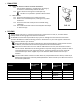
9. INCLINE CHART IMPORTANT: Refer to your mobility equipment manufacturer for the proper degree of incline/decline and chair direction before attempting ramp use. Never exceed your mobility equipment manufacturer recommendations. TO ESTABLISH THE PROPER RAMP LENGTH: Determine the incline that your chair is designed to climb. Measure the rise (distance from the top step, porch, van, etc. to the ground). Refer to Incline Chart to find proper ramp length.