
Dimensions Guide
Page 2 of 9
OVERVIEW
SCOPE OF WORK: PROVIDE PREFABRICATED MODULAR ALUMINUM ACCESS RAMPS AND STEPS
1. SUBMITTALS
1.1 Product Literature must be submitted with bid.
1.2 Warranty must be submitted with bid.
1.3 Shop Drawings: Include detailed shop drawings upon receipt of purchase order.
1.4 Engineering: Provide sealed professional engineering drawings or empirical independent test results upon
request.
2. QUALITY ASSURANCE
2.1 Manufacturer: EZ-ACCESS, a division of Homecare Products, Inc., 700 MILWAUKEE AVE. N, ALGONA, WA 98001-
7408. Toll free: (800) 451-1903 or Fax (800) 630-2350. Website: www.ezaccess.com. Any alternate
manufacturer must be approved prior to bid opening.
2.2 All components shall be reusable and shall be easy to disassemble and reassemble so the ramp system can be
relocated.
2.3 Design of all aluminum members shall conform to the 2018 edition of the International Building Code (IBC).
2.4 All exposed surfaces shall be smooth and free of sharp or jagged edges.
2.5 All components shall have a mill finish.
2.6 All fasteners shall be corrosion resistant.
2.7 Warranty: EZ-ACCESS, a division of Homecare Products, Inc., warrants its products to be free from defects in
manufacturing material and workmanship for a period of three years beginning at date of delivery of product.
This warranty excludes any defects resulting from abnormal use in installation, service, accidental or intentional
damage or any occurrences beyond the manufacturer’s control.
3. PRODUCTS
3.1 RAMP SECTIONS
3.1.1 Engineering
3.1.1.1 Ramp Sections shall be designed for a Uniform Live Load of 100 pounds per square foot
(psf) minimum and a concentrated vertical load of 300 pounds.
3.1.1.2 Aluminum structural design shall conform to the aluminum association specifications and
guidelines for aluminum structures.
3.1.2 Materials
3.1.2.1 Ramp Sections shall be constructed using 6000 series aluminum alloy with 6061-T6 or
6005-T5 being used for structural components.
3.1.3 Design
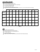
3.1.3.1 Ramp sections shall be prefabricated in 2’, 3’, 4’, 5’ and 6’ lengths in addition to a
distinctive 6’ starter ramp section.
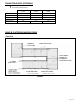
3.1.3.2 All ramp sections shall be designed for a 1:12 slope when assembled.
3.1.3.3 Ramp walking surface, for the standard 48”, 54”, and 60” ramps, shall be a clear width of
48”, 54”, and 60, respectively.
3.1.3.4 Ramp edges shall have a 4” tall (minimum) curb or a barrier which does not allow passage
of a 4” diameter sphere.
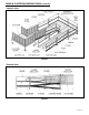
3.1.3.5 The walking surface of the ramp shall be continuous, without gaps, and shall be
approximately 1-1/4” x 6” self-mating aluminum deck with extruded slip resistant surface.
3.2 LANDINGS/PLATFORMS
3.2.1 Engineering
3.2.1.1 Landings/platforms shall be designed for a Uniform Live Load of 100 pounds per
square foot (psf) minimum and a concentrated static vertical load of 300 pounds.
3.2.2 Materials
3.2.2.1 Landings/platforms shall be constructed of 6000 series aluminum alloy with 6061-T6 or
6005-T5 for structural components.
3.2.3 Design
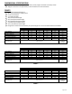
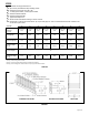
3.2.3.1 Landings/platforms shall be prefabricated in typical 65-1/2” square, 77-1/2” square,
65-1/2” x 77-1/2” rectangular or 65-1/2” x 89-1/2” rectangular sections.
3.2.3.2 Landings/platforms shall be designed for variable heights.
3.2.3.3 The walking surface of the landing/platform shall be continuous, without gaps, and
shall be comprised of approximately 1-1/4” x 6” high self-mating aluminum deck with
extruded slip resistant surface.