
Dimensions Guide
Page 3 of 9
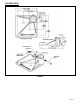
3.3 STEPS
3.3.1 Engineering
3.3.1.1 Step Systems shall be designed for a Uniform Live Load of 100 pounds per square foot
(psf) minimum and a concentrated vertical load of 300 pounds over an area of 4
square inches.
3.3.2 Materials
3.3.2.1 Step Systems shall be constructed using 6000 series aluminum alloy with 6061-T6 or 6005-
T5 being used for structural components.
3.3.3 Design
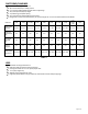
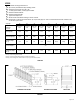
3.3.3.1 Step risers shall be between 7” maximum and 4” minimum (6” typical) high and shall
be closed.
3.3.3.2 Step treads shall be 11” minimum deep x 50-3/16” minimum wide between handrails,
56” between side rails.
3.3.3.3 The walking surface of the step shall be without gaps and shall be composed of self-
mating aluminum treads and riser closures with an extruded slip resistant surface.
3.4 LEGS
3.4.1 Engineering
3.4.1.1 The legs shall be designed to support the ramp and landing/platform sections (see
sections 3.1.1.1 and 3.2.1.1).
3.4.2 Materials
3.4.2.1 Legs shall be all aluminum construction alloy 6061-T6 or 6005-T5.
3.4.3 Design
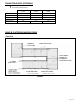
3.4.3.1 The legs shall allow for height and slope adjustments. Legs shall be designed so that
they will be perpendicular to the ground and vertical loads are transmitted axially
through them, regardless of slope.
3.4.3.2 All legs shall have through bolted polymer 7-3/8” x 7-3/8” feet.
3.5 GUARDS AND HANDRAILS
3.5.1 Engineering
3.5.1.1 Guards and handrails shall be designed to resist a single concentrated load of 200
pounds applied at any point and in any direction at the top of the guard or handrail
and to transfer this load through the supports to the structure.
3.5.1.2 Guards and Handrails shall be designed and constructed to resist a load of 50 pounds
per linear foot applied horizontally at the required guard height and a simultaneous
load of 100 pounds per linear foot applied vertically downward at the top of the
guard. Note: The loading of 3.5.1.1, 3.5.1.2, and 3.5.1.3 shall not be applied
simultaneously.
3.5.1.3 Guard infill (pickets, balusters, etc.) shall be designed and constructed to resist a 50-
pound horizontal load applied over a one square foot area at any point in the system.
3.5.2 Materials
3.5.2.1 All guards, handrails, and handrail brackets shall be aluminum construction alloy
6061-T6 or 6005-T5.
3.5.3 Design
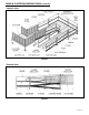
3.5.3.1 Handrail gripping surface shall be smooth and continuous throughout ramp sections,
steps, and landings/platforms, returning to a guard or wall that is not more than 1/4”
from the end of the handrail termination.
3.5.3.2 The handrail shall be 1-1/2” diameter tubing. The top of the handrail shall be 36”
above the walking surface. The height of the handrail above the finish surface “shall
be uniform, not less than 34” (864 mm) and not more than 38” (965 mm)”.
3.5.3.3 Optional child handrail shall be 1-1/2 “diameter tubing. The top of the child handrail
shall be 25” above the walking surface.
3.5.3.4 Guards shall form a protective barrier of 42” high, minimum. Guards shall be
designed such that a 4” sphere cannot pass through any opening.