
Instructions / Assembly

Page | 4
SET UP AND USE
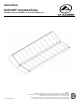
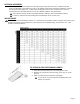
1. The ramp is shipped fully assembled. To unfold for use, position the folded ramp so that the top lip transition
plate (located on the end of the ramp that is labeled TOP) fully overlaps a secure, unobstructed, level landing
and is securely supporting the ramp (FIG. 1).
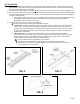
2. Unfold the ramp, exposing the slip-resistant tread surface, then center the ramp on the upper landing (FIG. 2).
3. Ensure that the surface area of both top lip transition plates fully overlaps a secure, unobstructed, level landing
enough to safely install provided clevis pins or other non-provided anchoring hardware, and rests firmly against
the upper landing (FIG. 3).
a. If the top lip transition plates are not long enough to fully overlap a secure, unobstructed, level landing,
a SUITCASE® Top Lip Extension (‘TLE’) is an available option (sold separately). See ‘OPTIONAL
ACCESSORY’ section for more information.
4. Securely anchor the ramp to the upper landing (FIG. 2).
Ensure that the ramp is securely anchored before each use.
a. TEMPORARILY: To attach temporarily using the provided clevis pins, position the ramp securely and
use the hole in each top lip transition plate as a template to drill corresponding ¼” holes into the
upper landing (ensure drilled holes are deep enough to fully seat each clevis pin). Fully insert a clevis
pin (FIG. 3) through the pre-drilled hole in each top lip transition plate and into the corresponding
drilled holes in the landing.
b. SEMI-PERMANENTLY: To attach semi-permanently using non-provided anchoring hardware,
position the ramp securely and use the hole in each top lip transition plate as a template to identify
anchor locations. Install non-provided anchoring hardware flush with the surface of each top lip
transition plate and ensure that it does not create a hazard.
Semi-permanent anchoring hardware is not provided.
When using non-provided anchoring hardware, follow hardware manufacturer’s
installation instructions, ensuring that hardware is of sufficient type and size to prevent
ramp slippage or undo movement.
FIG. 1
FIG. 2
FIG. 3