
Installation Guide

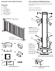


Post Installation with Separate Mounting Flange
Note: When installing “low profile” base covers with the separate
mounting flange, the horizontal thru bolts must be installed near
the bottom of the mounting flange.
1. Layout posts uniformly or as desired across entire project.
2. Ensure spacing between posts does not exceed 6 ft. for elevated decks
(or greater than local codes specify).
3. Starting at a corner post, attach post flange to deck/patio using appropriate
fasteners provided with the Post Kit. MAKE SURE TO USE ADDITIONAL
LUMBER BLOCKING UNDER THE DECK TO SECURELY FASTEN THE FLANGE!!!
In some instances, fully threaded lag screws may be necessary – but are
not included. LAG SCREWS LOOSEN OVER TIME AND REQUIRE
QUARTERLY SAFETY CHECKS.
4. Slide 3"x3" post over post flange and plum using level.
5. Drill ¼" hole (1 ½" above flange) front-to-back through the entire post and
post flange coming out on the back side. IT IS IMPORTANT TO DRILL
HOLES WITH POST PLUM.
6. Drill 2nd ¼" hole side-to-side.
Start hole 3/4" above the
flange base. Note that hole
patterns can be modified if
necessary. Additional screws
predrilled into post and flange
will firm-up post installation.
7. Fasten post to post flange
with 3 ½" bolt, washer, and
standard nut provided.
Washers must be placed
on both sides of the post.
8. After post is plum and securely
fastened, slide decorative
base cover (optional and sold
separately) over post covering
the post flange.
9. Secure next post using same
procedure. At this point you
may size (cut) and install
a railing section to verify
your desired layout. Then
continue to set the
remainder of the posts.
5
Post Mounts are installed with railing
sections in STEP 5. Mounts shown for
informational purpose only in this step.
IMPORTANT: Install
supporting lumber below
composite/wood decking
when surface mounting
posts to a deck. Fasten the
4" bolts through the decking
and supporting underside
lumber with the provided
tee nuts. We recommend
2" x 10"
IMPORTANT: When
installing the post
base into ACQ
lumber, use stainless
steel bolts
(not included)
Example A
1 1/2"
1 3/8"
3/4'
Stair
Adjustable Mount
Level
Mount
Mount can
rotate 180º
1 1/2"
1 3/8"
3/4'
IMPORTANT: The distance between
posts should not exceed 6 ft. when
installed above ground level. Always
refer to your local building department
for building code clarification.
6
For assistance call Madden Manufacturing
573-365-7085
Installation into wood/composite
decking/Non ACQ lumber:
1. Determine the 3"x 3" post location(s). Spacing between posts should be 6"
or less to meet IBC codes when installed 24" or higher above the ground.
2. We recommend the edge of the 5"x 5" base plate is fastened at least
1 3/4" in from the edge of the deck (do not lag screw into the rim joist
unless absolutely necessary).
3. Reinforce the decking with support lumber “backer board". A piece of
2"x 10" lumber cut to fit tightly between the joists and installed flat under
the decking works great.
4. Square up the post with the deck and mark all (4) holes with a pencil.
5. At your (4) pencil marks, drill a 1/4" hole through the decking and backer board.
6. Using a 7/16" socket bit in your drill, thread the 1/4"x 4" Thru Bolt into the
post plate, through the deck, and through the backer board. **
7. Thread the Tee Nut onto the 4" Thru Bolt underneath the decking
and support lumber(teeth up).
8. Tighten post firmly to deck, making sure post is plum, using shims if neccesary.
9. Slide on optional post base cover for a decorative look.
10. Attach post cap after railing has been installed using 1" fasteners
provided, or super glue.
** Note: The 4" Thru Bolt fits very tightly into the post base plate
(especially Textured Black Posts due to thicker powder coat finish) and in
some cases must be predrilled using a 1/4" drill bit.
Installation into concrete
1. Turn the post upside down on a hard surface
and prepare to drill larger holes in base plate.
Enlarge the (4) existing post base plate holes
to 5/16" (using a 5/16" drill bit).
2. Determine the 3"x 3" post
location(s). Spacing between
posts should be 6' or less to
meet IBC codes when installed
24" or higher above the ground.
3. We recommend the edge of the 5"x 5"
base plate is fastened at least 1 ½" in
from the edge of any concrete face
(assuming normal weight concrete).
4. Square up the post with the concrete
surface and mark all (4) holes with
a marker.
5. At your (4) marks, drill a 1/4"
masonry bit to 3 1/2" or deeper
hole into the concrete.
6. Fasten post in place with provided
1/4" x 3" Powers Wedge Bolts
7. Begin tightening the anchor with
socket wrench or impact wrench by rotating clockwise and applying
pressure in toward the concrete (make sure it is plumb).
8. Continue tightening the anchor until the head is firmly seated
against the post base plate. (Do not over tighten).
9. Slide on optional post base cover to hide fasteners. Attach post cap
after railing has been installed using 1" fasteners provided,
or use super glue.
Be careful to
drill holes at
slight angle
inward on top
plate