BTM510/511 MULTIMEDIA MODULE USER MANUAL www.lairdtech.
BTM510/511 Bluetooth® Multimedia Module TABLE OF CONTENTS CONTENTS BTM510/511 Bluetooth® Module ...3 Overview . ............................................. 3 BTM510/511 Key Features . .................. 3 Specifications .................................4 Detailed Specifications .......................... 4 Pin Definitions ....................................... 6 Operating Parameters ....................8 Voltage Specifications ........................... 8 Notes for PCB Layout .....................
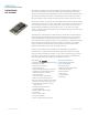
BTM510/511 Bluetooth® Multimedia Module OVERVIEW AND KEY FEATURES The BTM510 and BTM511 are low-power Bluetooth® modules designed for adding robust audio and voice capabilities. Based on the market-leading Cambridge Silicon Radio BC05 chipset, these modules provide exceptionally low power consumption with outstanding range. Supporting the latest Bluetooth Version 2.1+EDR specification, these modules provide the important advantage of secure simple pairing that improves security and enhances easy use.
BTM510/511 Bluetooth® Multimedia Module SPECIFICATIONS CATEGORIES FEATURE IMPLEMENTATION Wireless Specification Standards Supported Bluetooth® v2.1 + EDR Transmit Class Class 2 Frequency 2.402 – 2.
BTM510/511 Bluetooth® Multimedia Module SPECIFICATIONS CATEGORIES FEATURE IMPLEMENTATION Command Interface AT Instruction set Comprehensive control of connection and module operation, including extensions for Audio control. Direct mapping of GPIO to audio functions, e.g. Play, Volume, etc.
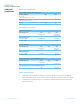
BTM510/511 Bluetooth® Multimedia Module SPECIFICATIONS 6 www.lairdtech.
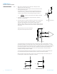
BTM510/511 Bluetooth® Multimedia Module SPECIFICATIONS Note: 1. 2. Reset input is active low. Input is pulled up to VDD_IN via 22k. Minimum reset pulse width is 5ms. LED drive pins are open drain outputs and hence the external circuit to the right should be used. The voltage on the module pad should be maintained below 0.5V in which case the Ron of the FET is around 20Ω.
BTM510/511 Bluetooth® Multimedia Module OPERATING PARAMETERS Operating Parameters Recommended Operating Conditions Operating Condition Min Max VDD_USB (USB compatibility not required) 1.7 3.6 VDD_USB (USB compatibility required) 3.1 3.6 VDD_IO 1.7 3.3 VDD_IN 3.0 3.6 Voltage Specifications Logic Levels (VUSB) Input Voltage Levels Min Typ Max Vih 0.625VDD_USB VDD_USB+0.3 Vil -0.3 0.25VDD_USB Voh (Iout = -4mA) 0.75VDD_USB VDD_USB Vol (Iout = 4mA) 0 0.
BTM510/511 Bluetooth® Multimedia Module AT Command Set Reference Introduction This document describes the protocol used to control and configure the BTM Bluetooth device. The protocol is similar to the industry standard Hayes AT protocol used in telephony modems which is appropriate for cable replacement scenarios, as both types of devices are connection oriented. Just like telephony modems, Laird Technologies’ devices power up in an unconnected state and will only respond via the serial interface.
BTM510/511 Bluetooth® Multimedia Module AT Command Set Reference Glossary of Terms Description 10 www.lairdtech.
BTM510/511 Bluetooth® Multimedia Module AT Command Set Reference Overview of the BTM product family BTM410 / BTM411 Chipset CSR BC4-Ext Bluetooth version 2.1 Features SSP, EIR, SCO (1), eSCO (1) Profiles SPP (1) external codec required BTM510 / BTM511 Chipset CSR BC5MM-Ext Bluetooth version 2.1 Features SSP, EIR, SCO, eSCO Profiles SPP, A2DP, AVRCP,HSP,HFP,DUN(DT) BTM520 / BTM521 11 www.lairdtech.com Chipset CSR BC5MM-Ext Bluetooth version 2.
BTM510/511 Bluetooth® Multimedia Module AT Command Set Reference BTM - AT Command Set This section describes the AT Command Set for a BTM module. This section is structured in functional groups of AT commands related to module configuration, Bluetooth profiles, hardware units and miscellaneous purposes. Assumptions 1. 2. 3. 4. 5. All commands are terminated by the carriage return character 0x0D, which is represented by the string in descriptions below this cannot be changed.
BTM510/511 Bluetooth® Multimedia Module AT Command Set Reference 3. ATZ {Hardware Reset and Emerge Into Boot Mode ‘n’} Forces the device through a hardware reset which means it will eventually come alive in the local command and unconnected mode. This allows changes to the non-volatile memory to take effect. The module will issue an OK response after the reset is complete and it is ready to receive commands once again.
BTM510/511 Bluetooth® Multimedia Module AT Command Set Reference 7. AT+BTF=”” {Set Friendly Name Temporarily} This sets the friendly name of this device as seen by other devices. The new name becomes immediately visible. Any name set by this command will be lost on next power cycle. Please refer to S register 593 (Table 4.1) too. Response: OK 8.
BTM510/511 Bluetooth® Multimedia Module AT Command Set Reference 14. AT+BTV, {SDP Query for Service } This command is used to interrogate the SDP database of the peer device for the service . It results in an ACL connection and then an SDP transaction.
BTM510/511 Bluetooth® Multimedia Module AT Command Set Reference 3. ATSn=? This will return the valid range of values for register n. For recognized values of n Response: Sn:(nnnn..mmmm)OK For unrecognized values of n Response: ERROR nn 4. AT&Fn This command will only work when the device is in local command and unconnected mode.
BTM510/511 Bluetooth® Multimedia Module AT Command Set Reference General S Registers Please refer to Appendix, Table 4.1 for a list of supported S Registers. The main purpose of S Registers is to make the device configuration persistent. All S Registers can be saved to non-volatile memory by AT&W. In some cases, an AT command and an S register exist for one and the same setting.
BTM510/511 Bluetooth® Multimedia Module AT Command Set Reference Inquiry Response Format The format of an inquiry result will be: ,,,, = 12 digit, hexadecimal; = six digit, hexadecimal; = printable ASCII character, enclosed by ‘ “ ‘ = signed two digits decimal = printable ASCII character whenever possible, otherwise a byte is displayed as ¬2 digit h
BTM510/511 Bluetooth® Multimedia Module AT Command Set Reference 6. AT+BTE=”” {Set Up Outgoing EIR Data} This command sets up outgoing EIR (extended inquiry response) data. Format: = printable ASCII character whenever possible, otherwise a two digit hexadecimal with preceding ‘\’ presenting one byte. Please note that the given data is written to baseband as it is (raw data) and no checks on the data format is performed.
BTM510/511 Bluetooth® Multimedia Module AT Command Set Reference 2. IO-Capability (S321) S-Register 321 defines the IO-capability of the device. The setting is used for IO-capability negotiations prior to SSP in order to identify whether the IO-capabilities of both devices are sufficient for MITM protection (if required). Table 3.4 lists possible values. S321 IO-Capability Comment 0 Display only The device has the capability to display or communicate a six digit decimal number.
BTM510/511 Bluetooth® Multimedia Module AT Command Set Reference 7. AT+BTW {Initiate SSP} This command initiates secure simple pairing (dedicated bonding) with a device whose Bluetooth address is . The correct term for this command’s action with respect to the Bluetooth specification 2.1+EDR [1] is “Dedicated Bonding”. Dedicated bonding means the exchange of link keys (pairing) without creating a connection to a particular profile or service immediately.
BTM510/511 Bluetooth® Multimedia Module AT Command Set Reference 9. Asynchronous SSP Messages Table 3.7 lists asynchronous messages which occur if MITM is enabled. The actually sent message depends on the combination of the IO capabilities of both ends. The combination of IO capabilities of both devices can also be insufficient for MITM protection. In that case the pairing will fail (PAIR 2 ). Please refer Table 5.6 in BT2.
BTM510/511 Bluetooth® Multimedia Module AT Command Set Reference AT Commands for Legacy Pairing 1. AT+BTW {Initiate Pairing} Provided the remote device is a Bluetooth 2.0 device or earlier and legacy pairing is not disabled (S323 = 0), this command is used to initiate legacy pairing with the device with . Legacy pairing refers to the mechanism of entering an identical PIN key on both ends.
BTM510/511 Bluetooth® Multimedia Module AT Command Set Reference AT Commands Managing Trusted Devices 1. AT+BTT? {List Trusted Device} This command is used to list the contents of the trusted device database. The link key is NOT displayed so the response is as shown below. If the list is empty then just the OK response is sent otherwise an OK is used to terminate the list. Use the command ATI6 to read the maximum size of the trusted device database.
BTM510/511 Bluetooth® Multimedia Module AT Command Set Reference 1. ATX”” {Send Data in Local Command and Connected Mode} This command is used to send data to the remote device when in local command and connected mode. The parameter is any string not more than 29 characters long whereby a non-printable character (\hh, see below) counts three characters. This restriction results from the maximum AT command length which is 34 (query by ATI15).
BTM510/511 Bluetooth® Multimedia Module AT Command Set Reference 5. ATO{Enter Data Mode} (letter ‘o’) Return to data mode. Assume that the module is in data mode after OK is received. Responds with an error if there is no Bluetooth SSO connection. Response: CONNECT 123456789012,< (if it was an incoming connection) CONNECT 123456789012,> (if it was an outgoing connection) Or Response: ERROR nn 6.
BTM510/511 Bluetooth® Multimedia Module AT Command Set Reference 8. SSO – S Registers The following table lists S registers for SSO profiles. Register Default Range Description S2 94 32..126 Escape sequence character. It is not ‘+’ by default as a Bluetooth serial link can be used to connect to a mobile phone which exposes an AT command set, which will in turn use ‘+’ as default. So if both used ‘+’, there will be confusion. 94 is the character ‘^’. S12 100 40..
BTM510/511 Bluetooth® Multimedia Module AT Command Set Reference 2. AT+BTG {Make Device Selectively Connectable Only} Make the BTM device connectable for the device with the Bluetooth address only. Connection requests from any other devices will be rejected. If the specified address is 000000000000 then incoming connections are accepted from any device, is as per AT+BTP without an address. The BTM device is not discoverable.
BTM510/511 Bluetooth® Multimedia Module AT Command Set Reference The second method is initiated by resetting the device and then ensuring that the text string “AT+BT&BISM&” is sent (where is the carriage return character). There is special code which looks out for this magic command and terminates the autoconnect cycle if it sees it and confirms to the host of that fact by sending an “OK” response. Response: OK 7.
BTM510/511 Bluetooth® Multimedia Module AT Command Set Reference Phase Dev. AT Command Comment Initiate connection A AT+SPD Initiate SPP connection from device A to device B. Asynchronous messages: “PAIR 0…” (pairing successful, A and B) “RING…” (B only) “CONNECT…” (connected, A and B) Connected A,B Any character entered on one end is displayed at the other end.
BTM510/511 Bluetooth® Multimedia Module AT Command Set Reference Figure 3.4: SPP example Device A - initiate connection, receiving data, command mode, disconnect Figure 3.5: SPP example Device B - incoming connection, receiving data, disconnection 2.2 ATA {Accept Incoming SPP Connection Request} Accept an incoming connection, which is indicated by the unsolicited string RING 123456789012 every second. 123456789012 is the Bluetooth address of the connecting device.
BTM510/511 Bluetooth® Multimedia Module AT Command Set Reference 2.4 AT+SPDL {Remake Connection} Make a SPP connection with the same device as that specified in the most recent AT+SPD command. An error will be returned if the ‘L’ modifier is specified AND a Bluetooth address. For backward compatibility, the following command fulfils the same purpose: ATDL Response: CONNECT 123456789012,> Or NO CARRIER 2.
BTM510/511 Bluetooth® Multimedia Module AT Command Set Reference 2.9 SPP – S Registers S Registers for SPP are summarized in Table 3.10. Register Default Range Description S0 0 Number of RING indication before automatically answering an incoming connection. A value of 0 disables autoanswer. If -1, then autoanswer on one RING and do NOT send RING/CONNECT response to the host.
BTM510/511 Bluetooth® Multimedia Module AT Command Set Reference 3.1 A2DP Example 1 This section gives an example of an A2DP connection between a Laird Technologies BTM device as Audio Sink (wireless speaker/ wireless headphones) and a PC with a built in Bluetooth device and Toshiba Bluetooth Stack 2.1 as Audio Source. The PC must support A2DP. If it is a different stack the procedure should be similar and follow the steps of: 1.) Device discovery 2.
BTM510/511 Bluetooth® Multimedia Module AT Command Set Reference Figure 3.6: A2DP example 1 – PC Bluetooth settings Figure 3.7: A2DP example 1 – Start discovery of Bluetooth devices 35 www.lairdtech.
BTM510/511 Bluetooth® Multimedia Module AT Command Set Reference Figure 3.8: A2DP example 1 – Select Bluetooth device (Click “Refresh” if Laird BTMM is not listed) Figure 3.9: A2DP example 1 – Confirm pairing (here: Secure Simple Pairing, no PIN required) Figure 3.10: A2DP example 1: Connection established 36 www.lairdtech.
BTM510/511 Bluetooth® Multimedia Module AT Command Set Reference Figure 3.11: A2DP example 1: New Bluetooth Audio Device in the Device Manager 3.2 A2DP Example 2 This section gives an example of an A2DP connection between a Laird Technologies BTM5xx device (A) as Audio Sink (wireless speaker/ wireless headphones) and another Laird Technologies BTM5xx device (B) as Audio source. Both BTM5xx devices are assumed to be connected via UART to a terminal program, e.g.
BTM510/511 Bluetooth® Multimedia Module AT Command Set Reference Phase Dev.
BTM510/511 Bluetooth® Multimedia Module AT Command Set Reference Figure 3.14: A2DP Example 2 –Initiate and Release Connection from Device B (Source) Figure 3.15: A2DP Example 2 – Accepting Connection and Volume Adjustment Device A (Sink) 3.3 Enable A2DP The advanced audio distribution profile (A2DP) is enabled by issuing ATS102=128. After verifying that a role has been set (S300 != 0) the S registers must be saved by AT&W.
BTM510/511 Bluetooth® Multimedia Module AT Command Set Reference 4. Set A2DP Device Class ATS515=$; AT&W; ATZ For compliance with the A2DP specification, [2] (and hence for successful interoperability to other devices) it is required to set up a valid device class code. The default device class code of a BTM device is 0x001F00 which is invalid for the A2DP profile.
BTM510/511 Bluetooth® Multimedia Module AT Command Set Reference 4.2 Output Gain Settings – A2DP Sink AT+GOU / AT+GOD AT+GOU – Increment audio output gain (volume). AT+GOD – Decrement audio output gain (volume). Response: OK ERROR 57 – Maximum gain level reached ERROR 58 – Minimum gain level reached The output gain level can be set directly using S register 589.
BTM510/511 Bluetooth® Multimedia Module AT Command Set Reference Task AT-Command / SRegister Comment Initiate outgoing A2DP connection AT+APD Response if accepted: “CONNECT 0123456789012,110D,>” Response if rejected: “NO CARRIER 110D” Close only A2DP connection “AT+APH” or “ATH110D” Response: “NO CARRIER 110D” if connection has existed and S329=0 “NO CARRIER” if connection has not existed and S329=0 Close all connections ATH* Response: “NO CARRIER ” for each profile that
BTM510/511 Bluetooth® Multimedia Module AT Command Set Reference 5 AVRCP (Audio Video Remote Control Profile) The “Audio/Video Remote Control Profile” is used to remotely control audio or video streaming devices. A device must be defined as either control (CT) or target (TG). Furthermore, one of four categories (Player/Recorder, Monitor/Amplifier, Tuner, Menu) must be assigned to a device. Version 1.0 of AVRCVP is supported.
BTM510/511 Bluetooth® Multimedia Module AT Command Set Reference Phase Dev. AT Command Comment Preparation BTM5xx AT&F* Restore factory default settings AVRCP profile is enabled per default in S102 AVRCP Control role is enabled per default in S301 ATZ Reset n/a 1.) Select “Options…” from the Bluetooth icon in the taskbar (Figure 3.16) Preparation PC 2.) Identify the PC’s Bluetooth Address in the “General” tab of Bluetooth Options (Figure 3.16) 3.
BTM510/511 Bluetooth® Multimedia Module AT Command Set Reference Figure 3.16: AVRCP Example 1 – Bluetooth Address of PC and AV Remote Control Service Figure 3.17: AVRCP Example 1 – Player Selection and Receiving Commands Display Setup 45 www.lairdtech.
BTM510/511 Bluetooth® Multimedia Module AT Command Set Reference Figure 3.18: AVRCP Example 1 – Secure simple pairing dialogue Figure 3.19: AVRCP Example 1 – BTM5xx Preparation and Connection Setup Figure 3.20: AVRCP Example 1 – BTM5xx Sending Commands and Connection Release Figure 3.21: AVRCP Example 1 – Incoming AVRCP commands (top-right corner of screen) 46 www.lairdtech.
BTM510/511 Bluetooth® Multimedia Module AT Command Set Reference 5.2 AVRCP - Control (CT) and Target (TG) This section describes AT Commands an S registers which are common to BTM5xx AVRCP Controller role and AVRCP Target role. 5.2.1 Initiate AVRCP Connection AT+AVD Initiate AVRCP control connection to Bluetooth address . The module must be configured as AVRCP Control by S register 301 = 1.
BTM510/511 Bluetooth® Multimedia Module AT Command Set Reference 5.3.3 Send Remote Control Command AT+AVC, Send a remote control command to a connected AVRCP target. Internally, a PASS THROUGH command is created and sent to the PANEL subunit of the AVRCP target. is the value for the actual remote control command. Valid values are specified in Table 3.20. Some Operation IDs can be replaced by mnemonics, see Table 3.
BTM510/511 Bluetooth® Multimedia Module AT Command Set Reference 5.4.4 PASS THROUGH Indication An incoming PASS THROUGH command will be indicated by an unsolicited message. AVPTI ,, For subunit_idhex see Table 3.21. For operation_idhex see Table 3.20. : ‘0’ is Button pushed ‘1’ is Button released 5.4.
BTM510/511 Bluetooth® Multimedia Module AT Command Set Reference Task AT-Command / S Register Comment Send a Unit Info request (Control) AT+AVU Response on command completion: “AVUR ,,,” Successful if = 0 Send a Subunit Info request (Control) AT+AVS (incomplete*) Response on command completion: “AVSR ,, ” Successful if = 0 *) only first word of the pagedata is being displayed in the AVSR response message Set Com
BTM510/511 Bluetooth® Multimedia Module AT Command Set Reference 51 www.lairdtech.
BTM510/511 Bluetooth® Multimedia Module AT Command Set Reference Unit / Subunit Type Value Monitor 0x00 Audio 0x01 Printer 0x02 Disc 0x03 Tape recorder player 0x04 Tuner 0x05 CA 0x06 Camera 0x07 Reserved 0x08 Panel 0x09 Bulletin board 0x0A Camera storage 0x0B Vendor unique 0x1C Reserved for all 0x1D Extended 0x1E Unit 0x1F Table 3.
BTM510/511 Bluetooth® Multimedia Module AT Command Set Reference Message Comment AVSR ,, Response to AT+AVS (SUBUNIT INFO Request), Indicates completion of command = statusdec: 0 – success 1 – fail 4 – timeout : requested page [0..31] : 1st word of requested page AVPTI ,, Indication of incoming Pass Through command : subunit id : see Table 3.
BTM510/511 Bluetooth® Multimedia Module AT Command Set Reference HSP Feature Support in HS Support in AG Specification BTM5xx Specification BTM5xx 1. Incoming audio connection M Yes M Yes 2. Outgoing audio connection M Yes O Yes 3. Audio connection transfer M Yes M Yes 4. Remote audio volume control O (1) O (1) M: mandatory O: optional (1) Supported planned for future firmware release Table 3.24: Headset Profile supported features on BTM5xx 6.
BTM510/511 Bluetooth® Multimedia Module AT Command Set Reference Connection status Outcome of AT+HSB (“AT+CKPD=200”) ACL connected (ATI63=1) Audio link will be initiated by AG Referred to as “Audio Connection Transfer from AG to HS” in HSPv1.2 Audio connected (ATI63=2) Audio link and ACL should be released by the AG, actual outcome depends on AG Table 3.25: Outcome of “AT+HSB” 6.1.3 Release Connection from Headset AT+HSH Release connection from local Headset instance.
BTM510/511 Bluetooth® Multimedia Module AT Command Set Reference 6.1.
BTM510/511 Bluetooth® Multimedia Module AT Command Set Reference 6.2.1 Initiate ACL Connection from AG (HSP) AT+HSGD Initiate ACL connection from local headset-gateway instance to remote device with . The remote device must support the headset role (HS) of the headset profile (HSP).
BTM510/511 Bluetooth® Multimedia Module AT Command Set Reference 6.2.7 Enable Automatic Alerting on SLC Establishment S345 S-Register 345 enables automatic alerting on ACL establishment. It contains a bitmask where bit0 corresponds to outgoing ACL connections and bit1 corresponds to incoming ACL connections. If automatic alerting is disabled (S345=0), it can be initiated manually by “AT+HSGC”. 6.2.
BTM510/511 Bluetooth® Multimedia Module AT Command Set Reference 6.2.12 AG - HSP Summary (HSG) Task AT-Command / S Register Comment Enable HSP-AG role S102 0x08 = AG role of HSP (bitmask), needs subsequent “AT&W” and “atz” to activate Initiate SLC from AG (HSP) AT+HSGD Responses: successful: “CONNECT 123456789012,1108,>” failed: “NO CARRIER” wrong state: “ERROR 63” profile disabled: “ERROR 59” Alert HS by RING or in-band ringing AT+HSGC An existing SLC is required.
BTM510/511 Bluetooth® Multimedia Module AT Command Set Reference 7. HFP (Hands-Free Profile) The Hands-free profile (HFP) defines how two devices supporting HFP shall interact with each other on a point-to-point basis. The use case for HFP is a hands-free unit that is connected wirelessly to an audio gateway. The audio gateway is typically a cellular phone.
BTM510/511 Bluetooth® Multimedia Module AT Command Set Reference 7.1 Hands-Free Unit Role (HF) Hands-free role is activated by setting flag 0x10 in S102 plus “AT&W” plus “atz“. Figure 3.24 outlines a block diagram with a BTM5xx in hosted operation mode. Telephone control (e.g set of buttons / keypad / display) Speaker Microphone Host Controller Echo Cancellation AT command interface Audio BTM5xx [HF] Figure 3.24 Hands-free unit block diagram 7.1.
BTM510/511 Bluetooth® Multimedia Module AT Command Set Reference 7.1.5 Answer Incoming Call from HF (#4_4.13) AT+HFCA Answer an incoming call. “ATA” will be sent to the AG. In return, the audio gateway shall update its “+CIEV” indicators (“call=1” and “callsetup=0”) and send appropriate messages to the HF. Upon receipt of a “+CIEV” message, HF will notify its host by a “HFI,” message. Please refer to section 7.1.15 on page 64. 7.1.
BTM510/511 Bluetooth® Multimedia Module AT Command Set Reference 7.1.12 Query Subscriber Number from HFG (#20_4.30) AT+HFS? Query subscriber numbers from HFG. “AT+CNUM” is sent to the HFG. HFG will send the subscriber number information, indicated on the HF by HF”+CNUM,,,””. An “OK” will be sent by HFG on termination, indicated on HF by the asynchronous message HF”CNUM,OK”.
BTM510/511 Bluetooth® Multimedia Module AT Command Set Reference 7.1.15 “+CIEV” Indicators Received from AG (#2) HFI””, (S333=1, default) HFI, Inform the HF-host about a “+CIEV” indicator message received from the connected audio gateway. S-Register 333 enables verbose mode for HFI indicators. Possible indicators are listed in Table 3.29.
BTM510/511 Bluetooth® Multimedia Module AT Command Set Reference HF”CLIP,ERROR” HFG has replied with ERROR to reception of “AT+CLIP<…>”. HF”+CLIP,n,m,1234567” A “calling line identification notification” (+CLIP:”1234567”,) has been received from the HFG. This message is sent by the HFG on incoming calls together with HF”RING”.
BTM510/511 Bluetooth® Multimedia Module AT Command Set Reference HF”CMEE,OK” HFG has replied with OK to reception of “AT+CMEE=1”. HF”CMEE,ERROR” HFG has replied with “ERROR” to reception of “AT+CMEE=1”. HFI<…> Indicator (+CIEV…) from audio gateway was received. Refer to section 7.1.15 on page 64. NO CARRIER 111E Service level connection to local HF-instance has been released. Please note section 6, page 85, too. 7.1.
BTM510/511 Bluetooth® Multimedia Module AT Command Set Reference 7.2 Audio Gateway Role (AG-HFP / HFG) Audio gateway role is activated by setting flag 0x40 in S102 plus “AT&W” plus “atz“. Please refer to Figure 3.23 (page 56) for a block diagram of an audio gateway with a BTM5xx in hosted operation mode. Table 3.28 shows the feature requirements for this profile and the level of support on BTM5xx.
BTM510/511 Bluetooth® Multimedia Module AT Command Set Reference 7.2.5 Signal Incoming Call from AG to HF (#4_4.13) AT+HFGC””, Signal an incoming call by sending “RING” and “+CLIP:””,” to HF periodically. The field represents the phone number of the ringing party.
BTM510/511 Bluetooth® Multimedia Module AT Command Set Reference Indicator name indicator_id Range of value Section in HFP spec. [5] Service 1 0..1 4.4 All call related sections Call 2 0..1 Call setup 3 0..3 Call held 4 0..2 Signal 5 0..5 4.5 Roam 6 0..1 4.6 Battery Charge 7 0..5 4.7 Table 3.31: AG indicators for “AT+HFGI..” 7.2.9 Send Operator String to HF (“+COPS…”, #2_4.
BTM510/511 Bluetooth® Multimedia Module AT Command Set Reference Response: OK OR: ERROR 05 OR: ERROR 67 AT+HFGS? This command returns a list of currently available subscriber number records which would be sent to the HF-unit on request (“AT+CNUM” issued by HF on the SLC).
BTM510/511 Bluetooth® Multimedia Module AT Command Set Reference 71 www.lairdtech.com HFG”VGS” Speaker gain setting message was received from HF (“+VGS:”) with n = gain [0..15]. HFG”VGM” Microphone gain setting message was received from HF (“+VGM:”) with n = gain [0..15]. HFG”AU1” Audio connection (SCO) has been established (= “audio on”). HFG”AU0” Audio connection (SCO) has been released (= “audio off”).
BTM510/511 Bluetooth® Multimedia Module AT Command Set Reference 7.2.
BTM510/511 Bluetooth® Multimedia Module AT Command Set Reference 8. DUN (Dial-Up Networking Profile) The Dial-up networking profile (DUN,[6]) defines protocols and procedures for the dial-up networking use case. Scenarios are the usage of a wireless modem or a cellular phone for dial–up Internet connections or the usage of a wireless modem or cellular phone to receive data calls by a PC. There are two roles defined: 1.
BTM510/511 Bluetooth® Multimedia Module AT Command Set Reference 8.2.1 Release DUN Connection AT+DUH The module must be in command mode so that AT-commands will be parsed. If the module is in data mode (S531=0, S507=2), toggle DSR line to change into command mode. OK will be sent to the host to confirm that that module is in command mode.
BTM510/511 Bluetooth® Multimedia Module AT Command Set Reference 2. Codec Gain Analogue input and output gains (Input Amplifier, Output Amplifier, Figure 3.25) can be set to one of 23 steps called “Gain Level”. To each gain level, an overall gain (dBr) is assigned, according to Table 3.34. The overall gain is formed by an analogue and a digital component as outlined in Table 3.34. Gain values can be specified either as gain level or as overall gain by separate S Registers.
BTM510/511 Bluetooth® Multimedia Module AT Command Set Reference Output Gain Level or Input Gain Level S589 or S590 Overall Gain (dBr) S689 or S690 Digital Component Analogue Component 9 -18.0 0 1 8 -21.0 0 0 7 -23.5 15 0 6 -27.0 14 0 5 -29.5 13 0 4 -33.0 12 0 3 -35.5 11 0 2 -39.0 10 0 1 -41.5 9 0 0 -45.0 8 0 Table 3.40: Gain Table Task AT-Command / SRegister Comment Set output gain level S589 [0..
BTM510/511 Bluetooth® Multimedia Module AT Command Set Reference 3. Mic Input Gain A microphone preamplifier which adds extra 24dB to input gain, is controlled by S-Register 415. The microphone amplifier is enabled by ATS415=1 and disabled by ATS415=0. Refer to Table 3.43. The first amplifier in Figure 3.28 represents the microphone preamplifier and the second amplifier represents the analogue component of the programmable audio input gain (refer to Table 3.40). Figure 3.
BTM510/511 Bluetooth® Multimedia Module AT Command Set Reference Register Default Range Description S415 0 0..1 Enable Microphone Input Gain, adds extra 24dB to input gain S419 6 0..6 Set sampling rate for Audio Loopback: 0 = 8 kHz 1 = 11.025 kHz 2 = 16 kHz 3 = 22.050 kHz 4 = 24 kHz 5 = 32 kHz 6 = 44.1 kHz S589 15 0..22 Codec output gain level (index of gain table) S590 15 0..22 Codec input gain level (index of gain table) S689 0 -450..
BTM510/511 Bluetooth® Multimedia Module AT Command Set Reference GPIO Pin (BTM510/511) Alternative Function Handshaking Wi-Fi Coexistence GPIO1 - BT_Active (1) GPIO2 DCD - GPIO3 DSR - GPIO4 RI - GPIO5 - BT_State/BT_Priority GPIO6 - Wlan_Active GPIO7 - Rf_Active GPIO8 DTR - (1) BT_Active = RxEnable OR TxEnable GPIO - Alternative Functions Bit 15 14 13 12 11 10 9 8 7 0 0 function mapping code / av_operation_id Default 0 0 0 0 0 0 0 6 5 4 FMS FME INV DIR PS
BTM510/511 Bluetooth® Multimedia Module AT Command Set Reference Register GPIO Default Range Comment S650 0 0..1 Mode for GPIO Config Registers: 0 = no mask; 1 = enable i/o pin state mask 0x0000 0..0xFFFF GPIO Configuration Registers S650 must be set to 0 to enable configuration access Controls Pin State, Pin Direction, Pin Inversion, Function Mapping Enable, Function Mapping Select and Function Mapping Code / av_operation_id. See Table 3.
BTM510/511 Bluetooth® Multimedia Module AT Command Set Reference Miscellaneous 1. SCO / eSCO Audio Link BTM modules provide an AT command to establish an SCO/eSCO audio connection between a pair of BTM modules (or BISM2). This enables the user to create bidirectional audio links independently from a particular Bluetooth profile. The only prerequisite is the existence of a Rfcomm link (serial port profile) between the modules.
BTM510/511 Bluetooth® Multimedia Module AT Command Set Reference 1.1 SCO / eSCO Asynchronous Messages The following asynchronous messages apply to SCO/eSCO connections. AUDIO ON (SCO) This response is sent to the host when a SCO channel has been established. AUDIO ON (eSCO) This response is sent to the host when a eSCO channel has been established. AUDIO OFF This response is sent to the host when an existing SCO/eSCO channel has been closed.
BTM510/511 Bluetooth® Multimedia Module AT Command Set Reference Task AT-Command Comment Get connection status of SPP ATI60 0 = not connected 1 = connected (local command mode) 2 = connected (remote command mode) identical with ATI9 Get connection status of A2DP ATI61 0 = not connected 1 = connected Get connection status of AVRCP ATI62 0 = not connected 1 = connected Get connection status of HSP-Headset ATI63 0 = not connected 1 = ACL connected 2 = audio connected Get connection status of
BTM510/511 Bluetooth® Multimedia Module AT Command Set Reference 5. Legacy Response Format (BISM2) Some BISM2 responses have been slightly changed on BTM modules in order to provide enhanced functionality. If required, a BISM2 compatible response format can be enabled by S Register 329. Table 3.63 shows the implications of enabled/disabled legacy response format. Task S-Register Comment Enable legacy response format (BISM2 compatible) S329 [0..
BTM510/511 Bluetooth® Multimedia Module AT Command Set Reference 6. UUIDs in “CONNECT”/”NO CARRIER” Messages In profiles where functionality and command set differs between both possible roles (asynchronous profiles), role indicating UUIDs are used in the “CONNECT” and “NO CARRIER” messages. HSP and HFP are asynchronous profiles. A2DP and AVRCP are treated as synchronous profiles because only one profile instance with one role selected can be initialised currently.
BTM510/511 Bluetooth® Multimedia Module AT Command Set Reference Figure 3.33: Page and Inquiry Scan Intervals and Windows 8. Sniff Mode Bluetooth connections are master/slave in nature. A master sends packets and a slave has to acknowledge that packet in the next timeslot. Timeslots in Bluetooth are 625 microseconds wide.
BTM510/511 Bluetooth® Multimedia Module AT Command Set Reference 9. Maximum RF-Tx Power Level The maximum RF transmit power level for all operation states (inquiring/connecting/in connection) is controlled by S541/S542. 10. Manufacturing Info String A string with manufacturing information can be retrieved by “ATI200”. 11. Bluetooth Version The Bluetooth version can be queried by “ATI18”. 12. Legacy Issues (BT2.0) There are some special cases if a legacy device (BT2.
BTM510/511 Bluetooth® Multimedia Module AT Command Set Reference Figure 3.35: BREAK capability in Ezurio Terminal 16. Append Bluetooth Address to Friendly Name 88 www.lairdtech.com If S Reg 593 is set to 1, then the last six hex digits of the Bluetooth address are automatically appended to the friendly name. This allows multiple devices with the same name in a neighborhood to be differentiated.
BTM510/511 Bluetooth® Multimedia Module AT Command Set Reference Appendix General S Registers The following table lists all general S Registers. Please not that this is not a complete listing of S Registers. Additional S registers, associated with a certain profile or feature are described in the appropriate section above. 89 www.lairdtech.com Register Deflt. Range Description S2 94 32..126 Escape sequence character.
BTM510/511 Bluetooth® Multimedia Module AT Command Set Reference 90 www.lairdtech.com Register Deflt. Range Description S334 0 0..1 Enable Extended Sdp Error Codes 0 - disable 1 – enable S504 0 0..1 Enable silent operation: Setting to 1 will force S0 to -1 and will suppress messages arising from connections or pairing. E.g., CONNECT, NO CARRIER, RING, PAIR, etc. Suppressing connection based messaged allows the device to be configured in cable replacement mode. S505 10 2..
BTM510/511 Bluetooth® Multimedia Module AT Command Set Reference 91 www.lairdtech.com Register Deflt. Range Description S512 1 0..7 Specify power up state. When set to 0, AT+BTO is required to open the device for Bluetooth activity. When set to 1, it proceeds to a state as if AT+BTO was entered. When set to 2, it will be discoverable only, similar to issuing AT+BTQ. When set to 3, it will be connectable but not discoverable e.g. AT+BTG When set to 4, it will be connectable and discoverable e.g.
BTM510/511 Bluetooth® Multimedia Module AT Command Set Reference 92 www.lairdtech.com Register Deflt. Range Description S520 9600 1200.. ..115200 Change to a standard baud rate. The effect is immediate and in fact the OK will be sent at the new baud rate. Only one of the following baud rates are accepted: 1200,2400,4800,9600,19200, 28800,38400,57600,115200. If S register 525=1, then the maximum baud rate is limited to 115200. S521 9521 1200.. ..921600 Change baud rate to non-standard value.
BTM510/511 Bluetooth® Multimedia Module AT Command Set Reference 93 www.lairdtech.com Register Deflt. Range Description S531 0 0..4 Specifies the mode on connection establishment. 0 = Normal, that data is exchanged between UART and RF. 1 = LOCAL_COMMAND. UART input is parsed by the AT interpreter and RF data is discarded. 2 = REMOTE_COMMAND. RF input is parsed by the AT interpreter and UART data is discarded.
BTM510/511 Bluetooth® Multimedia Module AT Command Set Reference 94 www.lairdtech.com Register Deflt. Range Description S552 $0122 $0..$fff This register specifies in each 4 bit nibble, how the DTR, DCD, RI output pins are controlled when in a Bluetooth connection Nibble 0..3 specifies the source for DTR 4..7 specifies the source for DCD 8..
BTM510/511 Bluetooth® Multimedia Module AT Command Set Reference Register Deflt. Range Description S560 15 15..120 Disconnect timeout in seconds. This timer specifies how long to wait for confirmation from the peer device and/or the underlying stack that the connection has been successfully torn down. There can be instances where a confirmation does not arrive and so in this case this timer is used to ‘close off’ the procedure and put the state machine back into a proper mode for new operations.
BTM510/511 Bluetooth® Multimedia Module AT Command Set Reference 96 www.lairdtech.com ATI Commands The following table lists all ATIn parameters supported by a BTM device. ATI commands provide general information about the BTM device and status information. Commands Information ATI0 The product name/variant. ATI1 The CSR firmware build number. ATI2 The AT firmware build number. For internal use only. ATI3 The AT firmware revision.
BTM510/511 Bluetooth® Multimedia Module AT Command Set Reference Commands Information ATI42 State information. Where the response values are as follows: 13 = NotOpen 14 = OpenIdle 15 = Ringing 16 = OnlineCommand 172 to 177 = waiting for connectable and/or discoverable where the lowest significant digit equates to the value stored in S Register 512 or 555. Note when n=16, ATI9 will return 1.
BTM510/511 Bluetooth® Multimedia Module AT Command Set Reference 98 www.lairdtech.com Error Responses Error Description 01 Register not recognized 02 Value for register is out of range 03 Incoming call NOT pending 04 No call to connect to.
BTM510/511 Bluetooth® Multimedia Module AT Command Set Reference Error Description 43 Unknown Audio Gateway Command 44 Busy, try later 45 Command or operation not allowed 46 No A2DP role has been set (see S register 300) 47 No AVRCP role has been set (see S register 301) 48 No AVRCP category has been set (see S register 302) 49 No AVRCP control connection 50 No A2DP or AVRCP connection currently incoming 51 Invalid operation ID (AVRCP) 52 Wrong AVRCP role 53 Command disabled by S-R
BTM510/511 Bluetooth® Multimedia Module AT Command Set Reference References [1] “Bluetooth Specification Version 2.1 + EDR [vol3]”, 26 July 2007 http://www.bluetooth.com/Bluetooth/Technology/Building/Specifications/ (click on “Core Specification v2.1 + EDR”) [2] “Advanced Audio Distribution Profile Specification” Rev. V12, 16/04/2007 http://www.bluetooth.com/Bluetooth/Technology/Works/A2DP.htm (link at bottom of page “Need more? View the Advanced Audio Distribution Profile (A2DP) 1.
BTM510/511 Bluetooth® Multimedia Module FCC Regulatory Statements BTM510 FCC and Industry Canada Statements The Final Equipment user manual must show the following statements: This device complies with part 15 of the FCC Rules. Operation is subject to the following two conditions: (1) This device may not cause harmful interference, and (2) this device must accept any interference received, including interference that may cause undesired operation.
BTM510/511 Bluetooth® Multimedia Module Declarations of Compliance EU DECLARATION OF CONFORMITY Manufacturer: Ezurio Ltd Product: BTM510 EU Directive: RTTE 1995/5/EC Conformity Assessment: Annex IV Reference standards used for presumption of conformity: Article Number: Requirement Reference standard(s): 3.1a Health and Safety EN 60950-1:2006 3.1b Protection requirements with respect to electromagnetic compatibility EN 301 489-1 V1.8.1 EN 301 489-17 V2.1.
BTM510/511 Bluetooth® Multimedia Module Declarations of Compliance EU DECLARATION OF CONFORMITY Manufacturer: Ezurio Ltd Product: BTM511 EU Directive: RTTE 1995/5/EC Conformity Assessment: Annex IV Reference standards used for presumption of conformity: Article Number: Requirement Reference standard(s): 3.1a Health and Safety EN 60950-1:2006 3.1b Protection requirements with respect to electromagnetic compatibility EN 301 489-1 V1.8.1 EN 301 489-17 V2.1.
BTM510/511 Bluetooth® Multimedia Module Mechanical Drawings BTM510 Mechanical Diagrams 104 www.lairdtech.
BTM510/511 Bluetooth® Multimedia Module Mechanical Drawings BTM510 Mechanical Diagrams 105 www.lairdtech.
BTM510/511 Bluetooth® Multimedia Module Mechanical Drawings BTM511 Mechanical Diagrams 106 www.lairdtech.
BTM510/511 Bluetooth® Multimedia Module Mechanical Drawings BTM511 Mechanical Diagrams 107 www.lairdtech.
4.) Ensure their is no exposed copper under the module on host p.c. board to avoid shorting to the test points on the underside of the module BTM510/511 Bluetooth® Multimedia Module Mechanical Drawings BTM511 Mechanical Diagrams 108 www.lairdtech.
A B C GPIO_6/WLAN_ACTIVE GPIO_7/RF_ACTIVE GPIO_1/BT_ACTIVE 1 VCC_IO 2 1 VCC_IO VCC_3V3 VCC_IO 5 5 MIC_A_N MIC_B_N MIC_A_P MIC_B_P R13 10K R8 10K R18 10K VCC_IO 2 D 1 2 R30 2K2 NF SW4 1 2 1 2 NF SW3 NF SW2 NF 3 4 R36 2K2 15pF C11 15pF C14 15pF C13 15pF C12 3 4 3 4 3 4 AGND L2 15n AGND AGND MIC_A_N_DIFF 15n L4 15n L3 15n AGND L1 NF 0R R31 NF 0R R28 NF 0R R34 1 R43 VCC_3V3 NF 0R R38 R32 0R 1 AGND R29 0R NF 15pF C7 R19 NF 0R SPKR_B_N
B C D Laird Technologies A 1 2 3 4 5 6 7 8 9 10 1 3 5 7 9 R62 10K 2 4 6 8 10 NF Header 2X5 JP4 R49 2 4 6 8 10 12 R68 1 1 1 0R 2 R67 2 4 6 AGND 2 10K R60 VCC_3V3 USB_MOD_D+ 10K R59 SPI_MOSI_PC SPI_CS_PC SPI_MISO_PC SPI_CLK_PC HSMC-A100-Q00J1 D1 LED_EXT1 130R R70 1 USB_GPIO_4/RI USB_RX USB_DCD SPI_MOSI_PC SPI_MISO_PC 1 2 3 4 5 6 7 8 9 10 R100 1K5 VCC_3V3 100n VCC OE2_ O0 I4 O1 I5 O2 I6 O3 I7 FTDI_EN JP3 20 19 18 17 16 15 14 13 12 11 1 3 2 2 4 6 U2 OUT VCC
B C D Laird Technologies A JP5 BLM18PG221SN1D 12 3 4 USB B Vcc DD+ GND RESET_FTDI L5 VDD_USB D3 5 D- 10K R84 NF C28 VDD_CONN USB_DCD USB_DTR USB_GPIO_4/RI USB_DSR 2 R85 1 VDD_CONN R77 Q1 USB_MOD_D+ USB+ USB- 2 3 5 1 USB_MOD_D- 1K N/F 2 USB_CTS USB_RTS USB_TX USB_RX NF 0R 2 NF 0R 2 2 0R R82 1 R94 1 2 0R R93 1 10K R78 R81 1 1 CN1 DC Power jack_2.
B C D A GPIO_6/WLAN_ACTIVE GPIO_7/RF_ACTIVE GPIO_1/BT_ACTIVE 1 VCC_IO 2 1 VCC_IO VCC_3V3 VCC_IO 5 5 MIC_A_N MIC_B_N MIC_A_P MIC_B_P R13 10K R8 10K R18 10K VCC_IO 2 1 2 R30 2K2 NF SW4 1 2 1 2 NF SW3 NF SW2 NF 3 4 R36 2K2 15pF C11 15pF C14 15pF C13 15pF C12 3 4 3 4 3 4 AGND L2 15n AGND AGND MIC_A_N_DIFF 15n L4 15n L3 15n AGND L1 NF 0R R31 NF 0R R28 NF 0R R34 1 R43 VCC_3V3 NF 0R R38 R32 0R 1 AGND R29 0R NF 15pF C7 R19 NF 0R SPKR_B_N
B C D Laird Technologies A 1 2 3 4 5 6 7 8 9 10 NF Header 10X1 J5 AGND AGND SPKR_B_P SPKR_A_P MIC_B_N MIC_A_N GPIO_4/RI 1 3 5 7 9 R62 10K 2 4 6 8 10 NF Header 2X5 JP4 R49 2 4 6 8 10 12 JP2 R68 1 1 1 0R 2 R67 2 4 6 AGND 2 10K R60 VCC_3V3 USB_MOD_D+ 10K R59 SPI_MOSI_PC SPI_CS_PC SPI_MISO_PC SPI_CLK_PC USB_DTR 1 2 3 4 5 6 7 8 9 10 R100 1K5 VCC_3V3 100n VCC OE2_ O0 I4 O1 I5 O2 I6 O3 I7 FTDI_EN 20 19 18 17 16 15 14 13 12 11 3 2 1 2 4 6 VCC OUT GND IN OE_ U3 4
B C D Laird Technologies A JP5 BLM18PG221SN1D USB B Vcc DD+ GND 12 3 4 RESET_FTDI L5 VDD_USB VDD_CONN NF Header 10X1 2 1 A 5 5 6 6 D3 5 D- 10K R84 NF C28 USB_DCD USB_DTR USB_GPIO_4/RI USB_DSR 2 R85 1 VDD_CONN R77 Q1 USB_MOD_D+ USB+ USB- 2 3 5 1 USB_MOD_D- 1K N/F 2 USB_CTS USB_RTS USB_TX USB_RX NF 0R 2 NF 0R 2 2 0R R82 1 R94 1 2 0R R93 1 10K R78 R81 1 1 CN1 DC Power jack_2.
BTM510/511 Bluetooth® Multimedia Module ORDERING INFORMATION ORDERING INFORMATION BTM510 BTM511 DVK-BTM510 DVK-BTM511 Bluetooth® Multimedia Module (external antenna) Bluetooth® Multimedia Module with integrated antenna Q2-2009 Development Board with BTM510 soldered in place Q1-2009 Development Board with BTM511 soldered in place Q2-2009 General Comments This is a preliminary datasheet. Please check with Laird Technologies for the latest information before commencing a design. If in doubt, ask.
Laird Technologies is the world leader in the design and manufacture of customized, performance-critical products for wireless and other advanced electronics applications.