
User's Manual

7
www.lairdtech.com
Laird Technologies
BTM510/511
Bluetooth
®
Multimedia Module
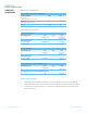
SPECIFICATIONS
The voltage on the module pad should be maintained below 0.5V
in which case the R
on
of the FET is around 20Ω. Provided that this
condition is met, then the current owing through the diode is:
3. The speaker output is capable of driving loads with a minimum
impedance of 16Ω directly.
4. The audio inputs can operate in either line input mode or microphone
mode. The input circuit has a two stage amplier – the rst stage
provides a xed 24dB gain and the second a variable gain of
between -3dB and 18dB. If an input gain of less than 24dB is selected,
then the rst stage is switched out and the module is operating in line
input mode.
I
led
=
VDD - V
F
Where V
F
is the forward bias voltage of the LED.
R + 20
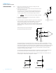
When operating in microphone mode the
microphone should be biased as follows:
MIC_AP
MIC_AN
Module
External Circuit
External Circuit
MIC_BIAS
15nH
15pF
15nH
15pF
The input impedance on the microphone inputs (in microphone mode) is typically 6kΩ. In order to
maintain the regulation on the MIC_BIAS pin, the current drawn must be in the range 0.2 – 1.23mA.
If the microphone draws less current than this, then an additional resistor to ground must be added to
pre-load the microphone output. The audio input is designed for use with inputs of between 1μA
and 10μA at 94dB SPL. If the biasing resistors are set to 1kΩ, this implies a microphone with a
sensitivity in the range -40dBV to -60dBV.
The low pass lter elements formed by the inductor and capacitor are required to eliminate RF pick
up on the microphone inputs and should be placed as close to the module as possible.
When operating in line input mode, the input can be connected directly to the module input pins
in either single or double ended conguration as follows:
AC
AC
Single ended Double ended
Note: 1. Reset input is active low. Input is pulled up to VDD_IN via 22k.
Minimum reset pulse width is 5ms.
2. LED drive pins are open drain outputs and hence the external circuit
to the right should be used.
VDD
Module External Circuit
R