
User's Manual


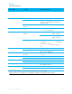


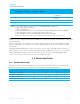

Table Of Contents
- Part # BL600-SA, BL600-SC, BL600-ST
- 3.1 SW Block diagram
- 3.3 Electrical Specifications
- 4.2 Measured waveforms
- 4.3 Peripheral block current consumption
- 5.1 Power management (includes brown-out and power on reset)
- 5.2 Clocks
- 5.3 Memory for smartBASIC application code
- 5.4 RF
- 5.5 UART Interface
- 5.6 SPI Bus
- 5.7 I2C Interface
- 5.8 General Purpose I/O and ADC
- 6.1 Circuit Components Required on Host PCB
- 6.2 BL600-Sx General PCB Layout on Host PCB
- 6.3 BL600-SA Layout on Host PCB
- 6.4 BL600-ST Layout on Host PCB
- 8.1 Introduction
- 8.2 Shipping
- 8.3 Reflow Parameters
- 9.2 OEM Responsibilities
- 10 Japan (MIC) Regulatory
- 11 CE Regulatory
- 12 EU DECLARATIONS OF CONFORMITY
- 14 ORDERING INFORMATION

BL600-Sx
Single Mode BLE Module
Pin No
Pin
Designation
Default
Function
Alternate
Function
Default
Direction
Notes
Comment
41
SIO_29
DIO
IN
1,2
Laird Devkit : UART_DCD
via CON12
42 SIO_30
DIO
IN 1,2 Laird Devkit : UART_RI via
CON12
43
GND
44 SIO_0
DIO
IN 1,2
Notes: 1. Secondary function is selectable in smartBASIC BASIC application
2.
DIO = Digital Input or Output
3.
AIN = Analog Input
4.
DIO or AIN functionality is selected using the GpioSetFunc() function in smartBASIC
5.
AIN configuration selected using GpioSetFunc() function
6.
I2C, UART, SPI controlled by xxxOPEN() functions in smartBASIC
7.
SIO_21 to SIO_24 are DIO by default when $autorun$ app runs on power up.
SIO lines can be configured through smartBASIC to be either inputs or outputs with weak or strong
pull-
ups or pull-downs.
At reset, all SIO lines are configured as the defaults shown above. In other words, BL600 module
shipped form production the loaded base FW, all the SIO pins (with “default function” of “DIO”
are inputs).
UART_RX, UART_TX, UART_CTS are all 3.3 v level logic. For example, when RX and TX are idle they
will be sitting at 3.3V. Conversely for handshaking pins CTS and RTS at 0v is treated as an assertion.
Pin 40 (nAutoRUN) is an input, with active low logic. In the development kit (DVK-BL600-sx) it is
connected so that the state is driven by the host’s DTR output line.
3.3 Electrical Specifications
3.3.1 Absolute Maximum ratings
Absolute maximum ratings for supply voltage and voltages on digital and analogue pins of the
Module are listed below; exceeding these values will cause permanent damage.
Parameter Min Max Unit
Voltage at VCC pin -0.3 +3.6 V
Voltage at GND pin 0 V
Voltage at SIO pin -0.3 VCC+0.3 V
Storage temperature -40 +85 ºC
9
www.lairdtech.com/wireless Laird