
User Manual


Page | 109 “How To” Guides
button to complete the update. This will send the rst communication to our IP server and activate
your account.
If you encounter any problems up to this point, please call 1-866-241-3400 to reach our tech
support personnel for help.
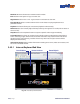
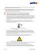
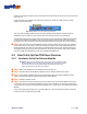
Fig. 144. EZWatchIP icon in system tray of task bar
After you click the Begin Update button, the login window will disappear and the round red
EZWatchIP icon will appear in your task bar. This icon indicates the service is operating.
The EZWatchIP program will check every 30 minutes to see if your Public IP Address has changed.
If it has, it will send the new address to our system so that the domain name you created (test.
ezwatchip.com, for example) will now be changed and allow you to access your system remotely.
■ Step 4 Now that you have your EZWatchIP service up and running, the next step is to congure
the DVR so that you can access it remotely. Following the steps on the next page will guide you
through opening your ports on your router or modem so that you can now use the system. Just
remember when you go to your remote location(s), when you are asked to enter your IP address
you will instead enter the domain name you created with EZWatch IP.
4.5 How To Set Up Pan/Tilt/Zoom Cameras
4.5.1 Hardware Set Up for Netcom Module
► Note To control a PTZ camera, each system must have (1) USB to RS-485
Netcom Module and (2) RS-485 communication wire. The recommended
communication wire is a twisted shielded two conductor cable. The
maximum distance to all cameras is 3000 ft.
■ Step 1 Insert your EZWatch Pro 4.0 Installation disc into your PC.
■ Step 2 Plug the USB to RS-485 Netcom Module into an available USB Port on the PC.
■ Step 3 The Windows Hardware Wizard will automatically detect the Netcom Module. Please
select the 'Install the software automatically' option in the Wizard.
■ Step 4 Reboot or Restart the PC.
■ Step 5 Connect the communication wire to the cameras. Then connect the opposite end of the
communication wire to the Netcom Module. Using a small screwdriver, connect the positive wire
(+) to the TX+/D+ terminal and connect the negative wire (-) to the TX-/D- terminal on the Netcom
Module.
This will correspond to the positive (+) and the negative (-) communication terminals on the PTZ
cameras. Insure all cables are fully seated.