STILO 24" / 30" / 36" / 48" Installation Instructions Use and Care Information Instructions d'installation Utilisez et d'entretien STIL24SS600-B STIL30SS600-B STIL36SS600-B STIL48SS600-B STIL30SS300-B STIL36SS300-B
READ AND SAVE THESE INSTRUCTIONS BEFORE YOU START INSTALLING THIS RANGEHOOD WARNING: - TO REDUCE THE RISK OF A RANGE TOP GREASE FIRE: a) Never leave surface units unattended at high settings. Boilovers cause smoking and greasy spillovers that may ignite. Heat oils slowly on low or medium setting. b) Always turn hood ON when cooking at high heat or when flambeing food (i.e. Crepes Suzette, Cherries Jubilee, Peppercorn Beef Flambé). c) Clean ventilating fans frequently.
. 1. 4. 2. When cutting or drilling into wall or ceiling, do not damage electrical electrical wiring wiring and and other hidden utilities. Ducted fans must always be vented to the outdoors. ALL WALL AND FLOOR OPENINGS WHERE THE RANGEHOOD IS INSTALLED MUST BE SEALED. This rangehood requires at least 24" of clearance between the bottom of the rangehood and the cooking surface or countertop. This hood has been approved by UL at this distance from the cooktop.
! WARNING • Electrical ground is required on this rangehood. • If cold water pipe is interrupted by plastic, nonmetallic gaskets or other materials, DO NOT use for grounding. • DO NOT ground to a gas pipe. • DO NOT have a fuse in the neutral or grounding circuit. A fuse in the neutral or grounding circuit could result in electrical shock. • Check with a qualified electrician if you are in doubt as to whether the rangehood is properly grounded.
RANGEHOOD DIMENSIONS ´ ´ ´ ´ Min.
Ref. Qty. 1 1 2 1 2.1 1 2.2 1 10 1 Ref. Qty. MAIN PARTS Components Product Components Hood Body, complete with: Controls, Light, Filters, Blower. Telescopic Chimney comprising: Upper Section Lower Section Damper ø 5 7/8" 2.1 Installation Components 7.2.1 2 Upper Chimney Section Fixing Brackets 7.3 1 Cooker Hood Fixing Brackets 12a 4 Screws 3/16" x 1 3/4" 12b 4 Screws 1/8" x 3/8" 12c 2 Screws 12d 2 Screws 1/8" x 3/8" Qty. 1 Documentation Instruction Manual 7.2.1 2.2 12a 7.
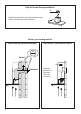
H Only for Ducted Venting Installation Install Damper that is included with the Hood before connecting to the ductwork.
1 Draw a vertical line on the supporting wall as high as practical, at the center of the area in which the hood will be installed. Draw a horizontal line at where the bottom edge of the hood will be located as indicated in the figure that is a minimum of 24" above cooking surface. 2 > ´ 6 3 4 2.1 5 2.1 7.2.1 6 56 34 12 1 12 5/8” 4 9/16” 4 9/16” 2 56 34 12 24” 24” ´ 6 Draw a horizontal line where indicated above the cooking surface. Place a bracket 7.2.
4 3 2X 11 I = 6x I = 6x 12a Installation screws provided must be secured with wall plugs (purchase separately). Insert the two screws 12a supplied with the hood into the Fixing Bracket as shown and do not tighten all the way to wall leaving 3/16" of the screw heads exposed. 6 5 I = 6x Use a level to insure that Fixing Bracket is level and then fully secure the two screws. 7 12c Hook the hood body onto the hood body fixing bracket 7.3.
9 Slightly widen the two sides of the upper chimney and hook them behind the brackets 7.2.1, making sure that they are well seated. L = 4x 12a 2.1 Install the 2 fixing brackets 7.2.1 to the middle and upper holes and secure with screws 12a as shown. 11 12 12bN = 4x Secure the sides to the brackets by using the 4 screws 12b. Slightly widen the two sides of the the lower chimney hood and hook them between the upper section and the wall, making sure that they are properly housed. 2.1 2.
Option 14 Non-Ducted Recirculation ¡ 15 12a Only for the recirculation version, connect the hood to the Air outlet. Fix the lower Bracket 7.2.1 with two screws 12a supplied as shown. 16 17 Fix the Ductless Diverter with two screws 12a supplied as shown. Slightly widen the two sides of the upper chimney and hook them behind the brackets and connect to the Ductless Diverter, making sure that they are well seated. 2.1 18 12bN = 4x Secure the sides to the brackets by using the 4 screws 12b.
ELECTRICAL INSTALLATION WITH CONNECTION CABLE GROUNDING INSTRUCTIONS This appliance must be grounded. In the event of an electrical short circuit, grounding reduces the risk of electric shock by providing an escape wire for the electric current. This appliance is equipped with a cord having a grounding wire with a grounding plug. The plug must be plugged into an outlet that is properly installed and grounded. WARNING - Improper grounding can result in a risk of electric shock.
20 Slightly widen the two sides of the the lower chimney hood and hook them between the upper section and the wall, making sure that they are properly housed. 13 2.1 2.2 21 N = 2x 12d Fix the the lower chimney hood laterally to the hood body using the 2 screws 12d supplied.
USE AND CARE INFORMATION For Best Results Start the rangehood several minutes before cooking to develop proper airflow. Allow the T1 T2 T3 T4 L rangehood to operate for several minutes after cooking is complete to clear all smoke and odors from the kitchen. T1 T2 T3 T4 L T1. Fan Off Button:Turn the blower Off. The fan can be operated by pressing any of the fan setting buttons.
Cleaning metal grease filters The filters must be cleaned every 2 months of operation, or more frequently for particularly heavy usage, and can be washed in a dishwasher. • Remove the Filters one at a time, pushing them towards the back of the unit and at the same time pulling downward. • Wash the Filters without bending them, and leave them to dry completely before replacing.
Wiring Diagram 16
FABER CONSUMER WARRANTY & SERVICE All Faber products are warranted against any defect in materials or workmanship for the original purchaser for a period of 1 year from the date of original purchase (requires proof of purchase). This warranty covers labor and replacement parts. Faber, at its option, may repair or replace the product or components necessary to restore the product to good working condition.
VEUILLEZ LIRE ET CONSERVER LA PRÉSENTE NOTICE AVANT DE COMMENCER L'INSTALLATION DE LA HOTTE DE CUISINE AVERTISSEMENT:-POUR RÉDUIRE LE RISQUE D'UN FEU DE GRAISSE SUR LA TABLE DE CUISSON : a) Ne laissez jamais sans surveillance les éléments de la surface de cuisson à température élevée. Les bouillonnements excessifs peuvent provoquer de la fumée et les débordements de graisse peuvent s'enflammer. L'huile doit être chauffée lentement, à une température basse ou moyenne.
3. 4. Lorsque vous faites une ouverture ou percez dans un mur ou le plafond, veillez à ne pas endommager les fils électriques ou d'autres dispositifs cachés. Les ventilateurs canalisés doivent toujours être raccordés à l'extérieur. TOUTE OUVERTURE DANS LE MUR OU LE PLANCHER À PROXIMITÉ DE LA HOTTE DOIT ÊTRE SCELLÉE. Un espace libre d'au moins 24 " est requis entre le bas de la hotte et la surface de cuisson ou le comptoir. Cette hotte a été homologuée par l'UL à cette distance de la surface de cuisson.
! AVERTISSEMENT • Une mise à la terre électrique est requise pour cette hotte. • N'UTILISEZ PAS un tuyau d'eau froide pour la mise à la terre si celui-ci est branché par des joints en plastique, par des rondelles non métalliques ou d'autres matériaux. • N'UTILISEZ PAS une conduite de gaz pour la mise à la terre. • N'INSTALLEZ PAS un fusible sur le circuit neutre ou le circuit de mise à la terre. La présence d'un fusible dans le circuit neutre ou de mise à la terre peut entraîner un choc électrique.
DIMENSIONS DE LA HOTTE ´ ´ ´ ´ Min.
Réf. Qté 1 1 2 1 2.1 1 2.2 1 10 1 Réf. Qté 7.2.1 2 7.3 1 12a 4 12b 4 12c 2 12d 2 Qté 1 PIÈCES PRINCIPALES Composants Composants du produit Bâti de la hotte, avec : Commandes,éclairages,filtres,ventilateur. Cheminéetélescopiquecomprenant: Section supérieure Section inférieure Registre ø 5 7/8" 2.
H Pour installation avec ventilation canalisée uniquement Installez le registre inclus avec la hotte avant de la raccorder aux conduits.
1 Tracez une ligne verticale sur le mur d'appui le plus haut que possible, au centre de l'emplacement où la hotte sera installée. Tracez une ligne horizontale à l'endroit correspondant au bas de la hotte comme représenté dans l'illustration. Cet emplacement doit se trouver à au moins 24" de la surface de cuisson. 2 > ´ 6 3 4 2.1 5 2.1 7.2.
4 3 2X 11 I = 6x I = 6x 12a Les vis d'installation fournies doivent être renforcées par des chevilles (achetées séparément). Insérez les deux vis 12a fournies avec la hotte dans la bride de fixation comme illustré. Ne les vissez pas complètement au mur, mais laissez libre 3/16" de la tête des vis. 6 5 I = 6x Utilisez un niveau pour vous assurer que la bride de fixation est à niveau, puis vissez à fond les deux vis.
10 9 L = 4x 12a Installez les 2 brides de fixation 7.2.1 à l'aide des trous percés au milieu et au haut, et fixez-les à l'aide de vis 12a comme illustré. 11 Écartez légèrement les deux côtés de la cheminée supérieure et engagez-les derrière les brides 7.2.1, en vous assurant qu'ils sont solidement ancrés. 2.1 12 Écartez légèrement les deux côtés de la section inférieure de la cheminée de hotte et assemblez-les entre la section supérieure et le mur, en vous assurant qu'ils sont correctement installés.
14 Option non canalisée avec recirculation¡ d'air 15 12a Pour la version à recirculation d'air uniquement, branchez la hotte à la sortie d'air. Fixez la bride 7.2.1 inférieure à l'aide de deux vis 12a fournies, comme illustré. 16 17 Fixez le déflecteur de recyclage à l'aide de deux vis 12a fournies, comme illustré.
INSTALLATION ÉLECTRIQUE AVEC CÂBLE DE CONNEXION INSTRUCTIONS DE MISE À LA TERRE Cet appareil doit être mis à la terre. La mise à la terre réduit le risque de choc électrique en cas de court-circuit, car elle fournit un fil d'évacuation au courant électrique. Cet appareil est muni d'un cordon présentant un fil de mise à la terre, avec une fiche de mise à la terre. La fiche doit être insérée dans une prise correctement installée et mise à la terre.
20 Écartez légèrement les deux côtés de la section inférieure de la cheminée de hotte et assemblez-les entre la section supérieure et le mur, en vous assurant qu'ils sont correctement installés. 29 2.1 2.2 21 Fixez la section inférieure de la cheminée de hotte latéralement sur le bâti de la hotte à l'aide des 2 vis 12d fournies.
INFORMATIONS POUR L'UTILISATION ET L'ENTRETIEN Pour de meilleurs résultats Activez la hotte quelques minutes avant de commencer à cuisiner pour créer un flux d'air T1 T2 quelques T3 minutes T4 L avoir fini de cuisiner pour adéquat. Laissez la hotte fonctionner après absorber toute la fumée et les odeurs de la cuisine. T1 T2 T3 T4 L T1. Bouton Arrêt du ventilateur : éteint le ventilateur. Le ventilateur peut être allumé en appuyant sur l'un ou l'autre des boutons de réglage.
Nettoyage des filtres à graisse métalliques Les filtres doivent être nettoyés tous les 2 mois d'utilisation, ou plus fréquemment en cas d'utilisation particulièrement intensive. Ils peuvent être lavés dans le lave-vaisselle. • Retirez les filtres un à un, en les poussant vers l'arrière de l'appareil et en les tirant vers le bas simultanément. • Lavez les filtres sans les plier et laissez-les sécher complètement avant de les remettre en place.
Schéma de câblage 32
GARANTIE LIMITÉE ET SERVICE FABER Tous les produits Faber font l'objet d'une garantie contre les défauts de matériel et de maind'œuvre,accordée à l'acheteur original pour une période d'un (1) an à compter de la date d'achat initiale (preuve d'achat requise). Cette garantie couvre les frais de main-d'œuvre et les pièces de rechange. À sa discrétion, Faber peut réparer ou remplacer le produit ou les composants nécessaires à remettre le produit en bon état de marche.
991.0433.