CHLOE' Installation Instructions Use and Care Information Instructions d'installation Utilisez et d'entretien Instrucciones de instalación Información de uso y cuidado CHLO28BK600 CHLO28GR600
READ AND SAVE THESE INSTRUCTIONS BEFORE YOU START INSTALLING THIS RANGEHOOD WARNING: - TO REDUCE THE RISK OF A RANGE TOP GREASE FIRE: a) Never leave surface units unattended at high settings. Boilovers cause smoking and greasy spillovers that may ignite. Heat oils slowly on low or medium setting. A KV@XR STQM GNNC .- VGDM BNNJHMF @S GHFG GD@S NQ VGDM l@LADHMF ENNC H D "QDODR Suzette, Cherries Jubilee, Peppercorn Beef Flambé). c) Clean ventilating fans frequently.
. When cutting or drilling into wall or ceiling, do not damage electrical wiring and other hidden utilities. 4. Ducted fans must always be vented to the outdoors. ALL WALL AND FLOOR OPENINGS WHERE THE RANGEHOOD IS INSTALLED MUST BE SEALED. This rangehood requires at least 24" of clearance between the bottom of the rangehood and the cooking surface or countertop. This hood has been approved by UL at this distance from the cooktop. This minimum clearance may be higher depending on local building codes.
ELECTRICAL REQUIREMENTS A 120 volt, 60 Hz AC-only electrical supply is required on a separate 15 amp fused circuit. A time-delay fuse or circuit breaker is recommended. The fuse must be sized per local codes in accordance with SGD DKDBSQHB@K Q@SHMF NE SGHR TMHS @R RODBHjDC NM SGD RDQH@K Q@SHMF OK@SD KNB@SDC HMRHCD SGD TMHS MD@Q SGD jDKC wiring compartment. ELECTRICAL INSTALLATION WITH WIRING BOX THIS UNIT MUST BE CONNECTED WITH COPPER WIRE ONLY.
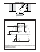
RANGEHOOD DIMENSIONS ´ ´ REAR DUCTED VENTING INSTALLATION SGD 'NNC RGNTKC BNLD RDS HM SGHR ONRHSHNM 7-11/16" 7 11/16" 5
Min. 24" 6 Min.
MAIN PARTS Components 12a Ref. Qty. Product Components 1 1 2 8 10 1 1 1 Hood Body, complete with: Controls, Light, Filters, Blower. Rear Section Recirculation Vent Grill Damper ø 5 7/8" Ref. Qty. Installation Components 12a 12b 4 2 12e 2 Screws 1/4" x 9/16" Screws 1/8"x3/8" (for Wiring Box mounting) Screws 1/8"x3/8" (for Recirculation Vent Grill mounting) Qty. Documentation 1 Instruction Manual H 2 10 1 12b I Parts needed - 6" Round Metal ductwork .
Choose your ducting method Ducted Venting Options Installation Rear Non Ducted - Recirculation Option 6" Requires purchase of Activated Charcoal Accessory When used in recirculation mode, To Reduce the Risk of Fire and Shock use only conversion kit Model FILTER1 9 9 Vertical and Horizontal Ducted Venting Installation with the optional Kit Chimney Requires purchase of Chimney accessory Vertical 6" 6" Horizontal 18 8
Installation Instructions 1 Draw a vertical line on the supporting wall as high as practical, at the center of the area in which the hood will be installed. 'UDZ D KRUL]RQWDO OLQH DW ZKHUH WKH ERWWRP HGJH RI WKH KRRG ZLOO EH ORFDWHG DV LQGLFDWHG LQ WKH ¿JXUH WKDW LV D PLQLPXP of 24" above Electric cooking surface and 30" above Gas.
3 4 L 2x L 2x Hook the Rear Section as shown in the image above onto the upper screws and fully secure. From inside fully secure the two lower screws (purchased separately). 5 Open the panel, unlock the security cable as VKRZQ 5HPRYH WKH ¿OWHUV E\ SXVKLQJ WKH OHYHU towards the back of the unit and at the same time pulling downward.
6 7 Remove the 4 screws as shown and take off the cover plates. Do not discard and set aside for future use. )URP LQVLGH WKH KRRG XVH D ÀDW KHDG VFUHZGULYHU DV VKRZQ LQ image above, to disconnect the left and right Connectors from the blower. 8 D G Unscrew the 2 screws (Posi-Drive) that hold the blower and unlock it from the initial position as shown in Image a. [ [ After removing blower rotate as shown until it is in the correct rear venting position as shown in Image b-c.
10 $WWDFK HDFK FKDUFRDO ¿OWHU WR WKH EODFN JULG RQ HDFK VLGH RI WKH EORZHU 3UHVV WKH FKDUFRDO ¿OWHU WLJKWO\ WR WKH EODFN JULG RQ WKH EORZHU VLGH DQG URWDWH WKH ¿OWHU FORFNZLVH WRZDUGV WKH IURQW of the hood) until it locks into place. Turn counterclockwise (towards the back of the hood) to remove.
Break the Hole in the Wiring Box to connect the Hood to Power Supply Cable. Remove the Wiring Box compartment cover by unscrewing the two screws. Pull the cable from the Power Supply through the Hole for the Electrical Connection to the Wiring Box.
A E B G C D F Installation of wiring connection 5HPRYH WKH FRYHU IURP WKH ¿HOG ZLULQJ FRPSDUWPHQW DO NOT turn on the power until installation is complete! Connect the Power Supply Cable to the rangehood. Connect the Green (Green and Yellow) ground wire under the Green grounding screw. Attach the White lead of the power supply to the White lead of the rangehood with a twist-on type wire connector.
Secure the Wiring Box as shown in the image with the 2 Screws (12b). 12b Attention: After the Wiring Box installation, place the Cable inside a Rear Section without stressing for the Cable. 16 Screw the two 12a screws into the Rear Section with the heads exposed by 1/4".
Only for the Rear Ducting Installation D G %HIRUH ¿[LQJ WKH %RG\ +RRG WR WKH Rear Section, Unscrew the 2 screws WR ¿[ WKH %ORZHU This operation will simplify the connect of Air outlet duct. [ E F Use this dimensional drawing to help with planning of duct connection. Install to the Roof or Wall attach ductwork. [ F 16 E After ¿[LQJ WKH %RG\ +RRG WR WKH 5HDU 6HFWLRQ ¿[ the Blower in the previously position with the same 2 screws.
Hook the hood body onto the upper screws (12a) of the mounted Rear Section, and then fully secure the screws. L 12a 2x 18 Complete the Securing of the Hood Body to the Rear Section by installing the two remaining 12a screws into the lower holes on the Rear Section. Secure all the 4 screws. M1 4x M1 = 4x M6x15 19 5HSODFH WKH ¿OWHUV LQWR WKH KRRG DQG ORFN WKH security cable as shown in the image to the right. Close the panel.
Vertical and Horizontal Ducted Venting Installation with the optional Kit Chimney Installation with the optional Kit Chimney - Preparation of Hood 1 Remove the 4 screws as shown and take off the cover plates. Do not discard and set aside for future use. 3 Open the panel, unlock the security cable as shown. 5HPRYH WKH ¿OWHUV E\ SXVKLQJ WKH OHYHU WRZDUGV WKH back of the unit and at the same time pulling downward.
4 Pull the Cable from the rear hole. Move the Cable from the rear of the Hood to the Top of the Hood. Fix the Cable in the hole on the Top of the Hood as show.
5 D G [ [ E F Unscrew the 2 screws that hold the blower and unlock it from the initial position as shown in Image a. After removing blower rotate as shown until it is in the correct rear venting position as shown in Image b-c. Use the two screws (Posi-Drive) that were removed to secure the blower as shown in Image d. 6 Re-secure the Cover Plate as shown with the screws removed previously.
7 A10 01A From inside the hood re-connect the Connectors on the left and right side shown in the image above. Installation with the optional Kit Chimney - Preparation of Wall 8 Draw a vertical line on the supporting wall as high as practical, at the center of the area in which the hood will be installed. 'UDZ D KRUL]RQWDO OLQH DW ZKHUH WKH ERWWRP HGJH RI WKH KRRG ZLOO EH ORFDWHG DV LQGLFDWHG LQ WKH ¿JXUH WKDW LV D PLQLPXP of 24" above Electric cooking surface and 30" above Gas.
9 > ´ [ ´ [ $ 5 1/8” 5 1/8” $ $ % % ´ 4 1/4” ´ 11 9/16” Mark the wall where indicated (A), 11 9/16" above the horizontal line and at 5 1/8" distance on the left and right of vertical line. Checking that the two marks are level. Insert two wall plugs and two screws into the holes as shown not completely (purchased separately). Mark the wall where indicated (B), 4 1/4" above the horizontal line and at 5 1/8" distance on the left and right of vertical line.
Installation with the optional Kit Chimney 10 4 L 2x +RRN DQG ¿[ WKH KRRG ERG\ RQWR the wall. 11 From inside fully secure the 4 screws 12a. L 4x 8 12 13 Use the four screws(included with Optional Telescopic Chimney Kit) to secure the angle bracket. Fix the bracket using the screws included with Optional Telescopic Chimney Kit.
14 Install Roof or Wall Cap purchased separately. Connect the 6" metal ductwork to the Roof or Wall Cap and then attach ductwork. 10 15 16 11 M1 4x N1 B N1 B Slightly widen the two sides of the upper chimney and hook them behind the brackets, making sure that they are well seated. 24 Secure the sides to the brackets by using the 4 screws .
Installation of wiring connection 17 A E B G 5HPRYH WKH FRYHU IURP WKH ¿HOG ZLULQJ FRPSDUWPHQW DO NOT turn on the power until installation is complete! Connect the Power Supply Cable to the rangehood. Connect the Green (Green and Yellow) ground wire under the Green grounding screw. Attach the White lead of the power supply to the White lead of the rangehood with a twist-on type wire connector.
USE AND CARE INFORMATION For Best Results 6WDUW WKH UDQJHKRRG VHYHUDO PLQXWHV EHIRUH FRRNLQJ WR GHYHORS SURSHU DLUÀRZ $OORZ WKH UDQJHKRRG WR RSHUDWH for several minutes after cooking is complete to clear all smoke and odors from the kitchen. S1 L T1 T2 T3 T4 Button Function L Turns the lights on/off at maximum strength. Press and hold the button for approximately 2 seconds to dim the Lights On/Off. T1 Turns the motor on/off at speed one. T2 Turns the Motor on at speed two.
"KD@MHMF LDS@K FQD@RD kKSDQR These can be washed in the dishwasher, and need to be cleaned whenever the S1 Led comes on or at least once every 2 months use, or more frequently if use is particularly intensive. Resetting the alarm signal • Turn the Lights and the Suction Motor off. • 3UHVV 7 DQG KROG IRU DW OHDVW VHFRQGV XQWLO /(' ÀDVKHV WKUHH WLPHV LQ FRQ¿UPDWLRQ Cleaning • 5HPRYH WKH ¿OWHU SXVKLQJ WKH OHYHU WRZDUGV WKH EDFN RI WKH unit and at the same time pulling downward.
Wiring Diagram + U ' B 28
FABER CONSUMER WARRANTY & SERVICE All Faber products are warranted against any defect in materials or workmanship for the original purchaser for a period of 1 year from the date of original purchase (requires proof of purchase). This warranty covers labor and replacement parts. Faber, at its option, may repair or replace the product or components necessary to restore the product to good working condition.
VEUILLEZ LIRE ET CONSERVER LA PRÉSENTE NOTICE AVANT DE COMMENCER L'INSTALLATION DE LA HOTTE DE CUISINE 5$13(22$,$-3 /.41 1Í#4(1$ +$ 1(204$ #f4- %$4 #$ &1 (22$ 241 + 3 !+$ #$ "4(22.-Ů a) Ne laissez jamais sans surveillance les éléments de la surface de cuisson à température élevée.
3.43$ .45$1341$ # -2 +$ ,41 .4 +$ /+ -"'$1 ½ /1.7(,(3Í #$ + '.33$ #.(3 Î31$ 2"$++Í$ Un espace libre d'au moins 24" est requis entre le bas de la hotte et la surface de cuisson ou le comptoir.
FICHE TECHNIQUE ÉLECTRIQUE 4MD @KHLDMS@SHNM CD BNTQ@MS @KSDQM@SHE CD UNKSR Đ Ű'Y DRS QDPTHRD RTQ TM BHQBTHS Đ ETRHAKD CHRSHMBS CD @LOĠQDR (K DRS QDBNLL@MCġ CeHMRS@KKDQ TM ETRHAKD SDLONQHRġ NT TM CHRINMBSDTQ +D ETRHAKD CNHS ĢSQD B@KHAQġ BNMENQLġLDMS @TW BNCDR DM UHFTDTQ ONTQ KDR B@Q@BSġQHRSHPTDR MNLHM@KDR ġKDBSQHPTDR CD Ke@OO@QDHK HMCHPTġDR RTQ K@ OK@PTD RHFM@KġSHPTD RHSTġD Đ KeHMSġQHDTQ CD Ke@OO@QDHK Đ OQNWHLHSġ CT BNLO@QSHLDMS CDR BĒAK@FDR DWSDQMDR INSTALLATION ÉLECTRIQUE AVEC BOÎTIER
DIMENSIONS DE LA HOTTE ´ ´ 7-11/16" 7 11/16" INSTALLATION AVEC VENTILATION CANALISÉE ARRIÈRE K@ GNSSD CDUQ@HS ģSQD KHUQĢD @UDB BDSSD BNMkFTQ@SHNM 33
Min. 24" 34 Min.
PIÈCES PRINCIPALES Composants 12a Réf. Qté Composants du produit 1 2 8 10 1 1 1 1 H Bâti de la hotte, avec : Commandes, éclai UDJHV ¿OWUHV YHQWLODWHXU section arrière Grille d'évent de recyclage Registre ø 5 7/8" 2 10 Réf.
Choisissez la méthode de canalisation Options d'installation avec ventilation canalisée Option sans canalisation, avec recyclage d’air 6" Arrière Exige l'achat de l'accessoire à charbon actif Pour réduire le risque d’incendie ou de choc électrique, lorsque l’appareil est utilisé en mode recyclage, utiliser uniquement le modèle FILTER1 en guise de trousse de conversion.
Notice d'installation 1 Tracez une ligne verticale sur le mur d'appui le plus haut que possible, au centre de l'emplacement où la hotte sera installée. Tracez une ligne horizontale à l'endroit correspondant au bas de la hotte comme représenté dans l'illustration. Cet emplacement doit se trouver à au moins 24" de la surface de cuisson, si elle est électrique, ou à 30" si elle est au gaz.
3 4 L 2x L 2x Engagez la section arrière sur les vis du haut, comme LOOXVWUp VXU O¶LPDJH FL GHVVXV HW ¿[H] OD IHUPHPHQW Depuis l’intérieur, vissez à fond les deux vis inférieures (achetées séparément). 5 Ouvrez le panneau et dégagez le câble de retenue comme illustré. Retirez les ¿OWUHV HQ SRXVVDQW VLPXOWDQpPHQW OH OHYLHU vers l'arrière de l'appareil et en le tirant YHUV OH EDV 1H MHWH] SDV OHV ¿OWUHV PDLV conservez-les pour plus tard.
6 7 Retirez les 4 vis comme illustré et enlevez les plaques GH UHFRXYUHPHQW 1H OHV MHWH] SDV JDUGH] OHV SRXU utilisation ultérieure. 8Dévissez les 2 vis (PosiDrive) qui retiennent le ventilateur et déverrouillezle de sa position initiale, comme illustré sur l’image A. Depuis l’intérieur de la hotte, utilisez un tournevis à lame plate comme illustré pour débrancher les connecteurs de gauche et de droite du ventilateur.
10 )L[H] OHV ¿OWUHV j FKDUERQ j OD JULOOH QRLUH GH FKDTXH F{Wp GX YHQWLODWHXU 3UHVVH] IHUPHPHQW OH ¿OWUH j FKDUERQ FRQWUH OD JULOOH QRLUH GH FKDTXH F{Wp GX YHQWLODWHXU HW IDLWHV WRXUQHU OH ¿OWUH dans le sens des aiguilles d'une montre (vers l'avant de la hotte) MXVTX j FH TX LO VRLW YHUURXLOOp HQ SODFH )DLWHV WRXUQHU GDQV OH sens contraire des aiguilles d'une montre (vers l'arrière de la hotte) pour l'enlever.
13 'pIRQFH] O¶RUL¿FH GX ERvWLHU de connexion pour brancher le câble reliant la hotte à l’alimentation. Retirez le couvercle du compartiment du boîtier de connexion en dévissant les deux vis. Tirez le câble de l’alimentation par le trou permettant le raccord électrique du boîtier de connexion.
14 A E B G C D F Réalisation des branchements Retirez le couvercle du compartiment des câblages externes. NE METTEZ PAS l'alimentation sous tension avant d'avoir terminé l'installation! Branchez le câble d'alimentation à la hotte. %UDQFKH] OH ¿O YHUW YHUW HW MDXQH GH PLVH j OD WHUUH VRXV OD YLV GH PLVH j OD WHUUH YHUWH %UDQFKH] OH ¿O EODQF GH O DOLPHQWDWLRQ DX ¿O EODQF GH OD KRWWH j O DLGH d'un connecteur verrouillé par rotation.
15 Fixez le boîtier de connexion comme illustré sur l’image à l’aide des 2 vis (12b). 12b Attention : Après l’installation du boîtier de connexion, placez le câble dans une section arrière, sans contrainte sur le câble. 16 Vissez les deux vis 12a dans la section arrière en laissant 1/4" de la tête des vis libre.
Pour l’installation avec canalisation arrière uniquement D $YDQW GH ¿[HU OH EkWL GH OD KRWWH sur la section arrière, dévissez les YLV ¿[DQW OH YHQWLODWHXU &HWWH PHVXUH VLPSOL¿HUD OH raccord de la canalisation de sortie d’air. G [ E F 8WLOLVH] FH SODQ GLPHQVLRQQHO SRXU YRXV DLGHU j SODQL¿HU OH raccord des canalisations. Raccordez le dispositif aux canalisations du plafond ou du mur.
17 Engagez le bâti de la hotte sur les vis du haut (12a) de la section arrière montée, puis vissez-les fermement. L 12a 2x 18 Fixez complètement le bâti de la hotte sur la section arrière en installant les deux vis 12a restantes dans les deux trous inférieurs sur la section arrière. Vissez les 4 vis. M1 4x M1 = 4x M6x15 19 5HPHWWH] OHV ¿OWUHV HQ SODFH GDQV OD KRWWH et verrouillez le câble de retenue comme illustré dans l’image à droite. Refermez le panneau.
Installation avec ventilation canalisée verticale et horizontale, avec la trousse de cheminée en option Installation avec la trousse de cheminée en option - Préparation de la hotte 1 Retirez les 4 vis comme illustré et enlevez les plaques GH UHFRXYUHPHQW 1H OHV MHWH] SDV JDUGH] OHV SRXU utilisation ultérieure.
4 Tirez le câble du trou arrière. Déplacez le câble de l’arrière de la hotte vers le haut de la hotte. Fixez le câble dans le trou du haut de la hotte comme illustré.
5 D G [ [ E F Dévissez les 2 vis qui retiennent le ventilateur et déverrouillez-le de sa position initiale, comme illustré sur l’image A. $SUqV DYRLU UHWLUp OH YHQWLODWHXU WRXUQH] OH FRPPH LOOXVWUp MXVTX¶j TX¶LO VH WURXYH GDQV OD SRVLWLRQ FRUUHFWH GH ventilation arrière, comme illustré sur les images B-C.
7 A10 01A Depuis l’intérieur de la hotte, rebranchez les connecteurs de gauche et de droite illustrés sur l’image ci-dessus. Installation avec la trousse de cheminée en option - Préparation du mur 8 Tracez une ligne verticale sur le mur d'appui le plus haut que possible, au centre de l'emplacement où la hotte sera installée. Tracez une ligne horizontale à l'endroit correspondant au bas de la hotte comme représenté dans l'illustration.
9 > ´ [ ´ [ $ 5 1/8” 5 1/8” $ $ % % ´ 4 1/4” ´ 11 9/16” Tracez un repère sur le mur à l'endroit indiqué (A), 11 9/16" au-dessus de la ligne horizontale et à une distance de 5 1/8" à droite HW j JDXFKH GH OD OLJQH YHUWLFDOH 9pUL¿H] VL OHV GHX[ PDUTXHV VRQW j pJDOLWp Insérez deux chevilles et deux vis dans les trous comme illustré et non complètement (achetées séparément).
Installation avec la trousse de cheminée en option 10 4 L 2x (QJDJH] HW ¿[H] OH EkWL GH OD KRWWH sur le mur. 11 Depuis l’intérieur, vissez à fond les 4 vis 12a. L 4x 8 12 13 Utilisez les quatre vis (incluses avec la trousse de cheminée télescopique en option) SRXU ¿[HU O¶pWULHU d’assemblage. Fixez l’étrier à l’aide des vis incluses avec la trousse de cheminée télescopique en option.
14 Installez le clapet de toiture ou le clapet mural acheté séparément. Raccordez le conduit métallique de 6" au clapet de toiture ou au clapet mural, puis raccordez les conduits. 10 15 16 11 M1 4x N1 B N1 B eFDUWH] OpJqUHPHQW OHV GHX[ F{WpV GH OD FKHminée supérieure et engagez-les à l’arrière des brides, en vous assurant qu'ils sont solidement ancrés.
Réalisation des branchements 17 A E B G C Retirez le couvercle du compartiment des câblages externes. D F NE METTEZ PAS l'alimentation sous tension avant d'avoir terminé l'installation! Branchez le câble d'alimentation à la hotte. %UDQFKH] OH ¿O YHUW YHUW HW MDXQH GH PLVH j OD WHUUH VRXV OD YLV GH PLVH j OD WHUUH YHUWH %UDQFKH] OH ¿O EODQF GH O DOLPHQWDWLRQ DX ¿O blanc de la hotte à l'aide d'un connecteur verrouillé par rotation.
INFORMATIONS POUR L'UTILISATION ET L'ENTRETIEN Pour de meilleurs résultats $FWLYH] OD KRWWH TXHOTXHV PLQXWHV DYDQW GH FRPPHQFHU j FXLVLQHU SRXU FUpHU XQ ÀX[ G DLU DGpTXDW /DLVVH] OD KRWWH IRQFWLRQQHU TXHOTXHV PLQXWHV DSUqV DYRLU ¿QL GH FXLVLQHU SRXU DEVRUEHU WRXWH OD IXPpH HW OHV RGHXUV GH OD FXLVLQH S1 L Bouton L T1 T2 T3 T4 S1 T1 T2 T3 T4 Fonction Allume/Éteint l'éclairage à la puissance maximale.
-DSSNX@FD CDR kKSQDR Ē FQ@HRRD LĢS@KKHPTDR Ils peuvent être lavés dans le lave-vaisselle et doivent être nettoyés lorsque le témoin DEL S1 s'allume ou au moins une fois tous les 2 mois d'usage, ou encore plus fréquemment en cas d'utilisation particulièrement intensive. Réinitialisation du signal d'alarme • Éteint l'éclairage et le moteur d'aspiration.
Schéma de câblage + U ' B 56
FABER CONSUMER WARRANTY & SERVICE All Faber products are warranted against any defect in materials or workmanship for the original purchaser for a period of 1 year from the date of original purchase (requires proof of purchase). This warranty covers labor and replacement parts. Faber, at its option, may repair or replace the product or components necessary to restore the product to good working condition.
LEA Y GUARDE ESTAS INSTRUCCIONES ANTES DE EMPEZAR LA INSTALACIÓN DE ESTA CAMPANA ADVERTENCIA: - PARA REDUCIR EL RIESGO DE INCENDIO DE GRASA: -TMB@ CDID K@R TMHC@CDR CD RTODQkBHD CDR@SDMCHC@R DM KNR @ITRSDR @KSNR +NR derrames por ebullición pueden causar humos y derrames de grasa que pueden encenderse. Caliente los aceites lentamente en un ajuste bajo o medio.
3. 4. Al cortar o perforar la pared o el techo, no dañe el cableado eléctrico ni otros servicios ocultos. Los ventiladores con conductos siempre deben tener salida al exterior. TODAS LAS ABERTURAS DE LA PARED Y EL PISO DONDE ESTÁ INSTALADA LA CAMPANA SE DEBEN SELLAR.
REQUISITOS ELÉCTRICOS 2D QDPTHDQD TM RTLHMHRSQN DKġBSQHBN CD UNKSHNR 'Y RNKN " DM TM BHQBTHSN RDO@Q@CN con fusible de 15 amperios. Se recomienda un fusible de retardo o un cortacircuitos.
DIMENSIONES DE LA CAMPANA ´ ´ 7-11/16" 7 11/16" INSTALACIÓN DE VENTILACIÓN DE CONDUCTOS TRASEROS K@ B@LO@A@ CDADQı@ UDMHQ DM DRS@ ONRHBHŃM 61
Mín. 24" 62 Mín.
PARTES PRINCIPALES Componentes 12a Ref. Cdad. Componentes del producto 1 1 10 1 Cuerpo de la campana, completo de: Controles, Luces, Filtros, Ventilador. 6HFFLyQ WUDVHUD 5HMLOOD GH YHQWLODFLyQ GH UHFLUFXODFLyQ Registro ø 5 7/8" H 2 10 Ref. Cdad.
Elija su método de conducción Instalación de opciones de ventilación con conductos Trasero Sin conductos - Opción de recirculación 6" 5HTXLHUH FRPSUD GH DFFHVRULR GH FDUEyQ activado Cuando se utiliza en el modo de recircuODFLyQ SDUD UHGXFLU HO ULHVJR GH LQFHQGLR \ GHVFDUJD HOpFWULFD XWLOLFH VyOR HO NLW GH FRQYHUVLyQ 0RGHOR ),/7(5 65 65 Instalación de ventilación con conductos verticales y horizontales con el kit de chimenea opcional Requiere compra de accesorio Chimenea Vertical 6" 6" Horiz
Instrucciones de instalación 1 'LEXMH XQD OtQHD YHUWLFDO HQ OD SDUHG GH VRSRUWH WDQ DOWR FRPR VHD SRVLEOH HQ HO FHQWUR GHO iUHD GRQGH VH LQVWDODUi OD FDPSDQD 'LEXMH XQD OtQHD KRUL]RQWDO HQ GRQGH VH XELFDUi HO ERUGH LQIHULRU GH OD FDPSDQD FRPR VH LQGLFD HQ OD ¿JXUD TXH HVWi D XQ PtQLPR GH VREUH OD VXSHU¿FLH GH FRFFLyQ HOpFWULFD \ VREUH OD GH JDV 2 Instalación de la sección trasera 4 5/16” 4 5/16” $ $ % % ´ 4 1/4” ´ 11 9/16” Marque la pared donde se indica (A), 11 9/16" sobre
3 4 L 2x L 2x (QJDQFKH OD VHFFLyQ SRVWHULRU FRPR VH PXHVWUD HQ OD imagen de arriba en los tornillos superiores y asegure completamente. Desde adentro, asegure completamente los dos tornillos inferiores (se compran por separado). 5 Abra el panel, desbloquee el cable de seguridad como se muestra. Quite los ¿OWURV HPSXMDQGR OD SDODQFD KDFLD OD SDUWH posterior de la unidad y al mismo tiempo WLUDQGR KDFLD DEDMR 1R GHVHFKH ORV ¿OWURV y reserve para uso futuro.
6 7 Retire los 4 tornillos como se muestra y quite las placas de cubierta. No deseche y reserve para uso futuro. Desde el interior de la campana, utilice un destornillador de cabeza plana, como se muestra en la imagen de arriba, para desconectar los conectores izquierdo y derecho del ventilador. 8 Desatornille los 2 tornillos (Posi-Drive) que sostienen el ventilador y desbloquéelo D GHVGH OD SRVLFLyQ LQLFLDO como se muestra en la Imagen a.
10 &RQHFWH FDGD ¿OWUR GH FDUEyQ D OD UHMLOOD QHJUD D FDGD ODGR GHO YHQWLODGRU 3UHVLRQH HO ¿OWUR GH FDUEyQ ¿UPHPHQWH FRQWUD OD UHMLOOD QHJUD HQ HO ODGR GHO VRSODGRU \ JLUH HO ¿OWUR HQ VHQWLGR horario (hacia la parte delantera de la campana) hasta que HQFDMH HQ VX OXJDU *LUH HQ VHQWLGR DQWLKRUDULR KDFLD OD SDUWH posterior de la campana) para quitar.
13 5RPSD HO DJXMHUR HQ OD FDMD de cableado para conectar la campana al cable de suministro de energía. Retire la cubierta del FRPSDUWLPLHQWR GH OD FDMD GH conexiones desenroscando los dos tornillos.
14 A E B G C D F Instalación de conexión de cableado Retire la tapa del compartimento de cableado de campo. 12 HQFLHQGD OD XQLGDG KDVWD TXH VH KD\D FRPSOHWDGR OD LQVWDODFLyQ &RQHFWH HO FDEOH GH OD IXHQWH GH DOLPHQWDFLyQ D OD FDPSDQD &RQHFWH HO FDEOH GH WLHUUD YHUGH YHUGH \ DPDULOOR GHEDMR GHO WRUQLOOR GH FRQH[LyQ D WLHUUD YHUGH &RQHFWH HO FDEOH EODQFR GH OD IXHQWH GH DOLPHQWDFLyQ DO cable blanco de la campana con un conector de cable tipo twist-on.
15 $VHJXUH OD FDMD GH FDEOHDGR como se muestra en la imagen con los 2 tornillos (12b). 12b Atención: 'HVSXpV GH OD LQVWDODFLyQ GH OD FDMD GH FDEOHDGR FRORTXH HO FDEOH GHQWUR GH XQD VHFFLyQ posterior sin tirarlo demasiado. 16 Atornille los dos tornillos 12a HQ OD VHFFLyQ SRVWHULRU FRQ ODV cabezas expuestas 1/4".
Solo para la instalación de conducto trasero D $QWHV GH ¿MDU HO FXHUSR GH OD FDPSDQD D OD VHFFLyQ WUDVHUD GHVWRUQLOOH ORV WRUQLOORV SDUD ¿MDU el ventilador. (VWD RSHUDFLyQ VLPSOL¿FDUi OD FRQH[LyQ GHO FRQGXFWR GH VDOLGD de aire. G [ E F 8WLOLFH HVWH GLEXMR GLPHQVLRQDO SDUD D\XGDU FRQ OD SODQL¿FDFLyQ GH OD FRQH[LyQ GHO FRQGXFWR ,QVWDOH HQ HO FRQGXFWR GH FRQH[LyQ GHO WHFKR o la pared.
17 Enganche el cuerpo de la campana en los tornillos superiores D GH OD VHFFLyQ trasera montada, y luego asegure completamente los tornillos. L 12a 2x 18 &RPSOHWH OD ¿MDFLyQ GHO FXHUSR GH OD FDPSDQD D OD VHFFLyQ WUDVHUD instalando los dos tornillos 12a UHVWDQWHV HQ ORV RUL¿FLRV LQIHULRUHV GH OD VHFFLyQ SRVWHULRU Asegure los 4 tornillos. M1 4x M1 = 4x M6x15 19 9XHOYD D FRORFDU ORV ¿OWURV HQ OD FDPSDQD y bloquee el cable de seguridad como se muestra en la imagen a la derecha.
Instalación de ventilación con conductos verticales y horizontales con el kit de chimenea opcional Instalación con el kit de chimenea opcional - Preparación de la campana 1 Retire los 4 tornillos como se muestra y quite las placas de cubierta. No deseche y reserve para uso futuro.
4 Tire del cable desde HO RUL¿FLR WUDVHUR Mueva el cable desde la parte posterior de la campana hasta la parte superior de la campana. )LMH HO FDEOH HQ HO RUL¿FLR HQ OD SDUWH superior de la campana como se muestra.
5 D G [ [ E F 'HVDWRUQLOOH ORV WRUQLOORV TXH VRVWLHQHQ HO YHQWLODGRU \ GHVEORTXpHOR GHVGH OD SRVLFLyQ LQLFLDO FRPR VH PXHVWUD HQ OD Imagen a. 'HVSXpV GH UHWLUDU HO YHQWLODGRU JLUH FRPR VH PXHVWUD KDVWD TXH HVWp HQ OD SRVLFLyQ FRUUHFWD GH YHQWLODFLyQ WUDVHUD como se muestra en la Imagen b-c. Use los dos tornillos (Posi-Drive) que se quitaron para asegurar el ventilador como se muestra en la Imagen d.
7 A10 01A Desde el interior de la campana, vuelva a conectar los conectores en los lados izquierdo y derecho que se muestran en la imagen de arriba.
9 > ´ [ ´ [ $ 5 1/8” 5 1/8” $ $ % % ´ 4 1/4” ´ 11 9/16” Marque la pared donde se indica (A), 11 9/16" por encima de la línea horizontal y a una distancia de 5 1/8" a la izquierda y derecha de la línea vertical. Comprobando que las dos marcas estén niveladas.
Instalación con el kit de chimenea opcional 10 4 L 2x (QJDQFKH \ ¿MH HO FXHUSR GH OD campana en la pared. 11 Desde adentro, asegure completamente los 4 tornillos 12a. L 4x 12 13 8 M L 4x Utilice los cuatro tornillos (incluidos con el kit de chiPHQHD WHOHVFySLFD RSFLRQDO SDUD ¿MDU el soporte angular. 79 )LMH HO VRSRUWH utilizando los tornillos que se incluyen en el kit de chimeQHD WHOHVFySLFD opcional.
14 Instale el techo o la tapa de pared comprados por separado. Conecte los conductos metálicos de 6 "al techo o a la tapa de pared y luego conecte los conductos. 10 15 16 11 M1 4x N1 B N1 B Ligeramente ensanche los dos lados de la chimenea superior y engánchelos detrás de los soportes, asegurándose de que estén bien asentados. 80 Asegure los lados a los soportes con los 4 tornillos.
17 Instalación de conexión de cableado A E B G C Retire la tapa del compartimento de cableado de campo. NO encienda la unidad hasta que se haya completado la instalaFLyQ &RQHFWH HO FDEOH GH OD IXHQWH GH DOLPHQWDFLyQ D OD FDPSDQD &RQHFWH HO FDEOH GH WLHUUD YHUGH YHUGH \ DPDULOOR GHEDMR GHO WRUQLOOR GH FRQH[LyQ D WLHUUD YHUGH &RQHFWH HO FDEOH EODQFR GH OD IXHQWH GH DOLPHQWDFLyQ DO FDEOH EODQFR GH OD FDPSDQD FRQ XQ FRQHFWRU GH cable tipo twist-on.
INFORMACIÓN DE USO Y CUIDADO Para mejores resultados (QFLHQGD OD FDPSDQD YDULRV PLQXWRV DQWHV GH FRFLQDU SDUD GHVDUUROODU XQ ÀXMR GH DLUH DGHFXDGR 'HMH TXH OD FDPSDQD IXQFLRQH GXUDQWH YDULRV PLQXWRV GHVSXpV GH TXH VH FRPSOHWH OD FRFFLyQ SDUD HOLPLQDU WRGR HO KXPR y los olores de la cocina. S1 L T1 T2 T3 T4 Botón Función L Enciende / apaga las luces a máxima potencia. 0DQWHQJD SUHVLRQDGR HO ERWyQ GXUDQWH DSUR[LPDGDPHQWH VHJXQGRV SDUD DWHQXDU HO HQFHQGLGR apagado de las luces.
+HLOHDY@ CD KNR kKSQNR CD FQ@R@ LDSēKHBNR (VWRV SXHGHQ ODYDUVH HQ HO ODYDYDMLOODV \ GHEHQ OLPSLDUVH FDGD vez que se enciende el S1 Led o al menos una vez cada 2 meses de uso, o con mayor frecuencia si el uso es particularmente intenso.
Diagrama de cableado + U ' B 84
FABER CONSUMER WARRANTY & SERVICE All Faber products are warranted against any defect in materials or workmanship for the original purchaser for a period of 1 year from the date of original purchase (requires proof of purchase). This warranty covers labor and replacement parts. Faber, at its option, may repair or replace the product or components necessary to restore the product to good working condition.
991.0527.