
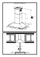
Installation Instructions

8
2
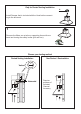
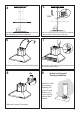
Draw a vertical line on the supporting wall as high as practical, at the center of the area in which
the hood will be installed.
Draw a horizontal line at where the bottom edge of the hood will be located as indicated in the gure
that is a minimum of 24" electric and 30" gas cooking surface clearance.
3
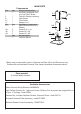
x6
x6
16 9/16 ”
4 9/16”
´
>
´
24” 30”
4 9/16”
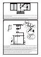
7.2.1
2.1
2.1
Draw a horizontal line where indicated at the bottom edge of the vent hood at the desired height above
the cooking surface.
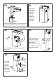
Place a bracket 7.2.1 on the wall as shown about 1 1/8" from the ceiling or upper limit, aligning the
centers(notch) with the vertical reference line and mark the wall at the centers of the holes in the bracket.
Place the second bracket 7.2.1 on the wall as shown, below the rst bracket, at the height of the
upper chimney section supplied and aligning the centers(notch) with the vertical line.
Mark the wall at the centers of the holes in the bracket and mark the point 1 and 2 for the Hood Body
installation as show (16 9/16" from the horizontal line and 4 9/16" from the vertical line).
Drill ø 5/16" holes at all the centers points marked (point 1,2,3,4,5,6) as shown.