GLASSY 30" GLASSY 36" TRATTO 30" TRATTO 36" Installation Instructions Use and Care Information Instructions d'installation Utilisez et d'entretien GLAS36SS300-B GLAS30SS300-B GLAS36SS600-B GLAS30SS600-B TRAT30SS600-B TRAT36SS600-B
READ AND SAVE THESE INSTRUCTIONS BEFORE YOU START INSTALLING THIS RANGEHOOD WARNING: - TO REDUCE THE RISK OF A RANGE TOP GREASE FIRE: a) Never leave surface units unattended at high settings. Boilovers cause smoking and greasy spillovers that may ignite. Heat oils slowly on low or medium setting. A KV@XR STQM GNNC .- VGDM BNNJHMF @S GHFG GD@S NQ VGDM l@LADHMF ENNC H D "QDODR Suzette, Cherries Jubilee, Peppercorn Beef Flambé). c) Clean ventilating fans frequently.
. 4. When cutting or drilling into wall or ceiling, do not damage electrical wiring and other hidden utilities. Ducted fans must always be vented to the outdoors. ALL WALL AND FLOOR OPENINGS WHERE THE RANGEHOOD IS INSTALLED MUST BE SEALED. This rangehood requires at least 24" of clearance between the bottom of the rangehood and the cooking surface or countertop. This hood has been approved by UL at this distance from the cooktop.
WARNING • Electrical ground is required on this rangehood. • If cold water pipe is interrupted by plastic, nonmetallic gaskets or other materials, DO NOT use for grounding. • DO NOT ground to a gas pipe. • DO NOT have a fuse in the neutral or grounding circuit. A fuse in the neutral or grounding circuit could result in electrical shock. q "GDBJ VHSG @ PT@KHjDC DKDBSQHBH@M HE XNT @QD HM CNTAS @R SN VGDSGDQ SGD Q@MFDGNNC HR properly grounded.
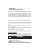
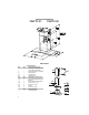
RANGEHOOD DIMENSIONS GLASSY 30" GLASSY 36" /16 10 1/4 ’’ 29 ’’ ’ 6’ 41 11 13/1 6 5/1 4 15 /16 ’’ ’’ 28 3/4’’ 37 3/8 ’’ 9 1/8 ’’ 5 3/4’’ 4 3/4’’ 21 1/4’’ 3 1/8’’ ’’ /16 5 3-1 9 15/16’’ 1/4’’ 1 7/1 6’’ 15 3/4’’ 14 30’’ - 3 6’’ 6’’ 3/1 MAIN PARTS Components Ref. Qty. Product Components 1 1 2 2.1 2.2 10 1 1 1 1 Hood Body, complete with: Controls, Light, Filters, Blower. Telescopic Chimney comprising: Upper Section Lower Section Damper ø 5 7/8" Ref. Qty.
RANGEHOOD DIMENSIONS TRATTO 30" TRATTO 36" MAIN PARTS Components Ref. Qty. Product Components 1 1 2 2.1 2.2 10 1 1 1 1 Hood Body, complete with: Controls, Light, Filters, Blower. Telescopic Chimney comprising: Upper Section Lower Section Damper ø 5 7/8" Ref. Qty. Installation Components 7.2.1 2 7.3 12a 12b 12c 12d 1 4 4 2 2 Upper Chimney Section Fixing Brackets Cooker Hood Fixing Brackets Screws 3/16" x 1 3/4" Screws 1/8" x 3/8" Screws Screws 1/8" x 3/8" Qty.
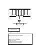
Min. 24" Parts needed - 6" Round Metal ductwork Available Accessories - Direct Connect Wiring Box sku # number: - WIREBOX +LJK &HLOLQJ &KLPQH\ .LW 8SSHU DQG /RZHU &KLPQH\ )OXH WR UHSODFH WKH RULJLQDO ÀXH V WR ¿W XS WR FHLOLQJV VNX +,*+ - Ductless Kit - Includes Ductless Diverter, Charcoal Filters - sku# DUCT4 - 6" Make-Up Air Damper Kit - MUDAMPER6 - 8" Make-Up Air Damper Kit - MUDAMPER8 - CFM Reducer Kit - CFMRED - Activated Charcoal Filter Accessory - sku# FILTER2 - Wireless Remote Control
H Only for Ducted Venting Installation Install Damper that is included with the Hood before connecting to the ductwork.
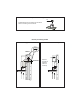
1 Draw a vertical line on the supporting wall as high as practical, at the center of the area in which the hood will be installed. 'UDZ D KRUL]RQWDO OLQH DW ZKHUH WKH ERWWRP HGJH RI WKH KRRG ZLOO EH ORFDWHG DV LQGLFDWHG LQ WKH ¿JXUH that is a minimum of 24" above cooking surface. 2 > ´ 6 3 4 2.1 5 2.1 7.2.1 6 56 34 12 2 24” 24” 12 1 1/16” 4 9/16” 4 9/16” 56 34 12 ´ 6 Draw a horizontal line where indicated above the hob.
4 3 2X 11 I = 6x I = 6x 12a Installation screws provided must be secured with wall plugs (purchase separately). ,QVHUW WKH WZR VFUHZV D VXSSOLHG ZLWK WKH KRRG into the Fixing Bracket as shown and do not WLJKWHQ DOO WKH ZD\ WR ZDOO OHDYLQJ RI WKH screw heads exposed. 6 5 I = 6x Use a level to insure that Fixing Bracket is level and then fully secure the two screws. 7 12c +RRN WKH KRRG ERG\ RQWR WKH KRRG ERG\ ¿[LQJ bracket 7.3.
10 9 Slightly widen the two sides of the upper chimney and hook them behind the brackets 7.2.1, making sure that they are well seated. L = 4x 12a 2.1 ,QVWDOO WKH ¿[LQJ EUDFNHWV WR WKH PLGGOH DQG XSSHU KROHV DQG VHFXUH ZLWK VFUHZV D DV VKRZQ 11 12 2.1 Slightly widen the two sides of the the lower chimney hood and hook them between the upper section and the wall, making sure that they are properly housed. 12bN = 4x 2.2 Secure the sides to the brackets by using the 4 screws 12b.
Option 14 Non-Ducted Recirculation ¡ 15 12a Only for the recirculation version, connect the hood to the Air outlet. Fix the lower Bracket 7.2.1 with WZR VFUHZV D supplied as shown. 16 17 Fix the Ductless Diverter with two screws 12a supplied as shown. 18 12bN = 4x Secure the sides to the brackets by using the 4 screws 12b. 12 Slightly widen the two sides of the upper chimney and hook them behind the brackets and connect to the Ductless Diverter, making sure that they are well seated. 2.
ELECTRICAL INSTALLATION WITH CONNECTION CABLE *5281',1* ,16758&7,216 7KLV DSSOLDQFH PXVW EH grounded. In the event of an electrical short circuit, grounding reduces the risk of electric shock by providing an escape wire for the electric current. This appliance is equipped with a cord having a grounding wire with a grounding plug. The plug must be plugged into an outlet that is properly installed and grounded. :$51,1* ,PSURSHU JURXQGLQJ FDQ UHVXOW LQ D ULVN RI electric shock.
20 21 2.1 Slightly widen the two sides of the the lower chimney hood and hook them between the upper section and the wall, making sure that they are properly housed. 14 2.2 N = 2x 12d Fix the the lower chimney hood laterally to the hood body using the 2 screws 12d supplied.
USE AND CARE INFORMATION For Best Results 6WDUW WKH UDQJHKRRG VHYHUDO PLQXWHV EHIRUH FRRNLQJ WR GHYHORS SURSHU DLUÀRZ $OORZ WKH rangehood to operate for several minutes after cooking is complete to clear all smoke and odors from the kitchen. T1 T2 T3 T4 L T1. Fan Off Button:Turn the blower Off. The fan can be operated by pressing any of the fan setting buttons. +ROG GRZQ WKLV EXWWRQ IRU VHFRQGV WR DFWLYDWH 'HOD\ 2II IXQFWLRQ ZKLFK ZLOO NHHS WKH IDQ 2Q IRU minutes and automaticall
"KD@MHMF LDS@K FQD@RD kKSDQR 7KH ¿OWHUV PXVW EH FOHDQHG HYHU\ PRQWKV RI RSHUDWLRQ RU PRUH frequently for particularly heavy usage, and can be washed in a dishwasher. • Remove the Filters one at a time, pushing them towards the back of the unit and at the same time pulling downward. • Wash the Filters without bending them, and leave them to GU\ FRPSOHWHO\ EHIRUH UHSODFLQJ ,I WKH VXUIDFH RI WKH ¿OWHU changes colour as time goes by, this will have absolutely no HIIHFW RQ WKH HI¿FLHQF\ RI WKH ¿OWHU LWVH
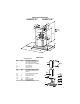
Wiring Diagram 991.0379.
)$%(5 &21680(5 :$55$17< 6(59,&( All Faber products are warranted against any defect in materials or workmanship for the original purchaser IRU D SHULRG RI \HDU IURP WKH GDWH RI RULJLQDO SXUFKDVH UHTXLUHV SURRI RI SXUFKDVH 7KLV ZDUUDQW\ FRYHUV labor and replacement parts. Faber, at its option, may repair or replace the product or components necessary to restore the product to good working condition.
VEUILLEZ LIRE ET CONSERVER LA PRÉSENTE NOTICE AVANT DE COMMENCER L'INSTALLATION DE LA HOTTE DE CUISINE AVERTISSEMENT:-POUR RÉDUIRE LE RISQUE D'UN FEU DE GRAISSE SUR LA TABLE DE "4(22.-Ů a) Ne laissez jamais sans surveillance les éléments de la surface de cuisson à température élevée.
3. 4. Lorsque vous faites une ouverture ou percez dans un mur ou le plafond, veillez à ne pas enCNLL@FDQ KDR kKR ĢKDBSQHPTDR NT Cf@TSQDR CHRONRHSHER B@BGĢR +DR UDMSHK@SDTQR B@M@KHRĢR CNHUDMS SNTINTQR ģSQD Q@BBNQCĢR Ē KfDWSĢQHDTQ 3.43$ .45$1341$ # -2 +$ ,41 .4 +$ /+ -"'$1 ½ /1.7(,(3Í #$ + '.33$ #.
AVERTISSEMENT q 4MD LHRD Đ K@ SDQQD ġKDBSQHPTD DRS QDPTHRD ONTQ BDSSD GNSSD q -e43(+(2$9 / 2 TM STX@T CeD@T EQNHCD ONTQ K@ LHRD Đ K@ SDQQD RH BDKTH BH DRS AQ@MBGġ O@Q CDR INHMSR DM OK@RSHPTD O@Q CDR QNMCDKKDR MNM LġS@KKHPTDR NT Ce@TSQDR L@SġQH@TW q -e43(+(2$9 / 2 TMD BNMCTHSD CD F@Y ONTQ K@ LHRD Đ K@ SDQQD q -e(-23 ++$9 / 2 TM ETRHAKD RTQ KD BHQBTHS MDTSQD NT KD BHQBTHS CD LHRD Đ K@ SDQQD +@ OQġRDMBD CeTM ETRHAKD C@MR KD BHQBTHS MDTSQD NT CD LHRD Đ K@ SDQQD ODTS DMSQ@ıMDQ TM BGNB ġKDBSQHPTD q "NMRTKSDY
DIMENSIONS DE LA HOTTE GLASSY 30" GLASSY 36" /16 10 1/4 ’’ 29 ’’ ’ 6’ 5/1 4 15 /16 ’’ 41 11 13/1 6 ’’ 28 3/4’’ 37 3/8 ’’ 9 1/8 ’’ 5 3/4’’ 4 3/4’’ 21 1/4’’ 3 1/8’’ ’ 3-1 5/1 6’ 9 15/16’’ 1/4’’ 1 7/1 6’’ 15 3/4’’ 14 30’’ 36’’ 3/1 6’’ PIÈCES PRINCIPALES Composants Réf. Qté Composants du produit 1 2 2.1 2.
DIMENSIONS DE LA HOTTE TRATTO 30" TRATTO 36" PIÈCES PRINCIPALES Composants Réf. Qté Composants du produit 1 2 2.1 2.2 10 1 1 1 1 1 Bâti de la hotte, avec : Commandes, pFODLUDJHV ¿OWUHV YHQWLODWHXU Cheminéetélescopiquecomprenant: Section supérieure Section inférieure Registre ø 5 7/8" Réf. Qté 2.1 7.2.
Min. 24" Pièces requises - Conduit métallique 6" circulaire Accessoires disponibles %RvWLHU GH FRQQH[LRQ GLUHFWH 1R G DUWLFOH :,5(%2; - Trousse de cheminée pour plafonds hauts - Conduit de cheminée supérieur et inférieur SRXU UHPSODFHU OH FRQGXLW RULJLQDO SRXU SODIRQGV MXVTX j 1R G DUWLFOH +,*+ 7URXVVH VDQV FRQGXLW &RPSUHQG GpÀHFWHXU GH UHF\FODJH ¿OWUHV j FKDUERQ 1R G DUWLFOH '8&7 'LVSRVLWLI G DSSRUW G DLU 08'$03(5 'LVSRVLWLI G DSSRUW G DLU 08'$03(5 - Réducteur
H Pour installation avec ventilation canalisée uniquement Installez le registre inclus avec la hotte avant de la raccorder aux conduits. Choisissez la méthode de canalisation I Options d'installation avec ventilation canalisée Sans canalisation - Option de recirculation 6" Verticale Horizontale Exige O DFKDW GH O DFFHVVRLUH j charbon actif.
1 7UDFH] XQH OLJQH YHUWLFDOH VXU OH PXU G DSSXL OH SOXV KDXW TXH SRVVLEOH DX FHQWUH GH O HPSODFHPHQW où la hotte sera installée. 7UDFH] XQH OLJQH KRUL]RQWDOH j O HQGURLW FRUUHVSRQGDQW DX EDV GH OD KRWWH FRPPH UHSUpVHQWp GDQV O LOOXVWUDWLRQ &HW HPSODFHPHQW GRLW VH WURXYHU j DX PRLQV GH OD VXUIDFH GH FXLVVRQ 2 > ´ 6 3 4 2.1 5 2.1 7.2.
4 3 2X 11 I = 6x 12a /HV YLV G LQVWDOODWLRQ IRXUQLHV GRLYHQW rWUH UHQIRUFpHV par des chevilles (achetées séparément).
10 9 L = 4x 12a ,QVWDOOH] OHV EULGHV GH ¿[DWLRQ j O DLGH GHV WURXV SHUFpV DX PLOLHX HW DX KDXW HW ¿[H] OHV j O DLGH GH YLV D FRPPH LOOXVWUp 11 Écartez légèrement les deux côtés de la cheminée supérieure et engagez-les derrière les brides 7.2.1, en vous assurant qu'ils sont solidement ancrés. 2.1 12 2.
14 Option non canalisée avec ¡ recirculation d'air 15 12a 3RXU OD YHUVLRQ j UHFLUFXODWLRQ G DLU XQLTXHPHQW EUDQFKH] OD KRWWH j OD VRUWLH G DLU 16 Fixez la EULGH LQIpULHXUH j O DLGH GH deux vis D IRXUQLHV FRPPH LOOXVWUp 17 )L[H] OH GpÀHFWHXU GH UHF\FODJH j O DLGH GH deux vis 12a fournies, comme illustré.
INSTALLATION ÉLECTRIQUE AVEC CÂBLE DE CONNEXION ,16758&7,216 '( 0,6( ¬ /$ 7(55( &HW DSSDUHLO GRLW rWUH PLV j OD WHUUH /D PLVH j OD WHUUH UpGXLW OH ULVTXH GH FKRF pOHFWULTXH HQ FDV GH FRXUW FLUFXLW FDU HOOH IRXUQLW XQ ¿O G pYDFXDWLRQ DX FRXUDQW pOHFWULTXH &HW DSSDUHLO HVW PXQL G XQ FRUGRQ SUpVHQWDQW XQ ¿O GH PLVH j OD WHUUH DYHF XQH ¿FKH GH PLVH j OD WHUUH /D ¿FKH GRLW rWUH LQVpUpH GDQV XQH SULVH FRUUHFWHPHQW LQVWDOOpH HW PLVH j OD WHUUH $9(57,66(0(17 8QH PLVH j OD WHUUH LQDGpTXDWH SHXW entra
20 21 2.1 Écartez légèrement les deux côtés de la section inférieure de la cheminée de hotte et assemblez-les entre la section supérieure et le mur, en vous assurant qu'ils sont correctement installés. 2.2 N = 2x 12d Fixez la section inférieure de la cheminée de hotte latéralement sur le bâti de la KRWWH j O DLGH des 2 vis 12d fournies.
INFORMATIONS POUR L'UTILISATION ET L'ENTRETIEN Pour de meilleurs résultats $FWLYH] OD KRWWH TXHOTXHV PLQXWHV DYDQW GH FRPPHQFHU j FXLVLQHU SRXU FUpHU XQ ÀX[ G DLU DGpTXDW /DLVVH] OD KRWWH IRQFWLRQQHU TXHOTXHV PLQXWHV DSUqV DYRLU ¿QL GH FXLVLQHU SRXU absorber toute la fumée et les odeurs de la cuisine. T1 T2 T3 T4 L T1 %RXWRQ $UUrW GX YHQWLODWHXU pWHLQW OH YHQWLODWHXU /H YHQWLODWHXU SHXW rWUH DOOXPp HQ DSSX\DQW VXU O XQ RX O DXWUH GHV ERXWRQV GH UpJODJH Tenez ce bouton enfoncé pend
-DSSNX@FD CDR kKSQDR Ē FQ@HRRD métalliques /HV ¿OWUHV GRLYHQW rWUH QHWWR\pV WRXV OHV PRLV d'utilisation, ou plus fréquemment en cas d'utilisation SDUWLFXOLqUHPHQW LQWHQVLYH ,OV SHXYHQW rWUH ODYpV GDQV le lave-vaisselle. • 5HWLUH] OHV ¿OWUHV XQ j XQ HQ OHV SRXVVDQW YHUV O DUULqUH de l'appareil et en les tirant vers le bas simultanément. • /DYH] OHV ¿OWUHV VDQV OHV SOLHU HW ODLVVH] OHV VpFKHU complètement avant de les remettre en place.
Schéma de câblage 991.0379.
*$5$17,( /,0,7e( (7 6(59,&( )$%(5 7RXV OHV SURGXLWV )DEHU IRQW O REMHW G XQH JDUDQWLH FRQWUH OHV GpIDXWV GH PDWpULHO HW GH PDLQ G °XYUH DFFRUGpH j O DFKHWHXU RULJLQDO SRXU XQH SpULRGH G XQ DQ j FRPSWHU GH OD GDWH G DFKDW LQLWLDOH SUHXYH G DFKDW UHTXLVH &HWWH JDUDQWLH FRXYUH OHV IUDLV GH PDLQ G °XYUH HW OHV SLqFHV GH UHFKDQJH ¬ VD GLVFUpWLRQ )DEHU SHXW UpSDUHU RX UHPSODFHU OH SURGXLW RX OHV FRPSRVDQWV QpFHVVDLUHV j UHPHWWUH OH SURGXLW en bon état de marche.
B ' B