INCA HC Installation Instructions Use and Care Information Instructions d'installation Utilisez et d'entretien INHC29SS600-B INHC29SS400
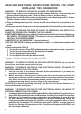
READ AND SAVE THESE INSTRUCTIONS BEFORE YOU START INSTALLING THIS RANGEHOOD WARNING: - TO REDUCE THE RISK OF A RANGE TOP GREASE FIRE: a) Never leave surface units unattended at high settings. Boilovers cause smoking and greasy spillovers that may ignite. Heat oils slowly on low or medium setting. b) Always turn hood ON when cooking at high heat or when flambeing food (i.e. Crepes Suzette, Cherries Jubilee, Peppercorn Beef Flambé). c) Clean ventilating fans frequently.
. 4. When cutting or drilling into wall or ceiling, do not damage electrical wiring and other hidden utilities. Ducted fans must always be vented to the outdoors. ALL WALL AND FLOOR OPENINGS WHERE THE RANGEHOOD IS INSTALLED MUST BE SEALED. This rangehood requires at least 24" of clearance between the bottom of the rangehood and the cooking surface or countertop. This hood has been approved by UL at this distance from the cooktop. This minimum clearance may be higher depending on local building codes.
! WARNING • Electrical ground is required on this rangehood. • If cold water pipe is interrupted by plastic, nonmetallic gaskets or other materials, DO NOT use for grounding. • DO NOT ground to a gas pipe. • DO NOT have a fuse in the neutral or grounding circuit. A fuse in the neutral or grounding circuit could result in electrical shock. • Check with a qualified electrician if you are in doubt as to whether the rangehood is properly grounded.
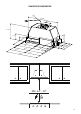
RANGEHOOD DIMENSIONS 47 " Min.
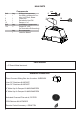
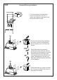
MAIN PARTS Ref. Qty. 1 1 2 1 8 1 10 1 Ref. Qty. 12e 2 Qty. 1 H Components Product Components Hood Body, complete with: Controls, Light, Filters, Blower. Power cord Recirculation Vent Grill Damper ø 5 7/8" H H Installation Components Screws 1/8" x 3/8" (for Recirculation Grill mounting) I Documentation Instruction Manual I I I Parts needed - 6" Round Metal ductwork .
H Only for Ducted Venting Installation Install Damper that is included with the Hood before connecting to the ductwork.
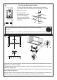
LATION Fitting the Hood canopy Installation Instructions FORE FITTING THE HOOD TO THE WALL UNIT, PROCEED AS FOLLOWS: 1 the wires to the Commands at the connectors. the wires to the Light at the con- can be installed directly on the of the wall unit (Minimum 650 mm ooker Hob). pening in the bottom of the wall unit, ood until the side supports snap into LQ 0 ´ 495 13 ´ 0 26 - 675 ´ Cut out the opening in the underside of the cabinet as shown in Figure 1.
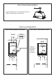
3.b Horizontal Ducting Installation 2 1/2” > For horizontal(rear) ducting there must be a minimum of 2 1/2" of space open between the back of the Hood Insert and the wall. [ For a horizontal ducting installation the motor needs to be unsecured by first removing the 12 screws as shown.
4 Non-Ducted Recirculation Option For Non-Ducted Recirculation venting route the ductwork to a location above the hood where the discharge is vented back into the room. Use the included Recirculation Vent Grill to cover the opening. Secure the grill with the 2 screws provided in the Install Kit. ´ Required Activated Charcoal Filter Accessory - sku # - FILTER1 (purchased separately) See page 11 Section 7 for installation instructions of Activated Charcoal Filter Accessory. 5 2x Min.
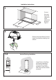
6 ELECTRICAL INSTALLATION WITH CONNECTION CABLE GROUNDING INSTRUCTIONS This appliance must be grounded. In the event of an electrical short circuit, grounding reduces the risk of electric shock by providing an escape wire for the electric current. This appliance is equipped with a cord having a grounding wire with a grounding plug. The plug must be plugged into an outlet Max. 33 7/16” that is properly installed and grounded. INSTALLATION WARNING - Improper grounding can result in a risk of electric shock.
LINER DIMENSIONS LINER DIMENSIONS / DIMENSIONS DU CADRE FIGURE MOD. INCA BIG ESB RIF. N.DIS. 352_731.1 FIGURE 1 R DIMENSIONS / DIMENSIONS DU CADRE Standard Liner 30 Stainless (LINE30ST) designed for 30” wide installations Cadre Standard 30 Axier Inoxydable (620000304) peut être employée les hottes encastrable sur mesure de 30" ) mesure de 30" DATA 24-Nov-10 Standard Liner 30 Stainless (LINE30ST) designed for 30” wide installations.
FOR INSTALLATION WITH LINERS ! WARNING When building a custom hood, always follow all applicable codes and standards. The Inca HC SS can be used with custom cabinetry WARNING and hoods 30" wide and up. Choose either a building a custom hood, custom linerWhen or our Standard Liner always follow all applicable designed forcodes 30"and and 36" wide standards. installations.
USE AND CARE INFORMATION For Best Results Start the rangehood several minutes before cooking to develop proper airflow. Allow the T1 T2 T3 T4 L rangehood to operate for several minutes after cooking is complete to clear all smoke and odors from the kitchen. T1 T2 T3 T4 L T1. Fan Off Button:Turn the blower Off. The fan can be operated by pressing any of the fan setting buttons.
fixing pin lever. Cleaning metal grease filters The metal grease filters can be cleaned in hot detergent solution or washed in the dishwasher. They should be cleaned • Remove grease filters. every 2 months, or more frequently if use is particularly heavy. • Remove the filter, pushing the lever towards the back of the unit and at the same time pulling downward.
Wiring Diagram 16 991.0350.
FABER CONSUMER WARRANTY & SERVICE All Faber products are warranted against any defect in materials or workmanship for the original purchaser for a period of 1 year from the date of original purchase (requires proof of purchase). This warranty covers labor and replacement parts. Faber, at its option, may repair or replace the product or components necessary to restore the product to good working condition.
VEUILLEZ LIRE ET CONSERVER LA PRÉSENTE NOTICE AVANT DE COMMENCER L'INSTALLATION DE LA HOTTE DE CUISINE AVERTISSEMENT:-POUR RÉDUIRE LE RISQUE D'UN FEU DE GRAISSE SUR LA TABLE DE CUISSON : a) Ne laissez jamais sans surveillance les éléments de la surface de cuisson à température élevée. Les bouillonnements excessifs peuvent provoquer de la fumée et les débordements de graisse peuvent s'enflammer. L'huile doit être chauffée lentement, à une température basse ou moyenne.
3. 4. Lorsque vous faites une ouverture ou percez dans un mur ou le plafond, veillez à ne pas endommager les fils électriques ou d'autres dispositifs cachés. Les ventilateurs canalisés doivent toujours être raccordés à l'extérieur. TOUTE OUVERTURE DANS LE MUR OU LE PLANCHER À PROXIMITÉ DE LA HOTTE DOIT ÊTRE SCELLÉE. Un espace libre d'au moins 24" est requis entre le bas de la hotte et la surface de cuisson ou le comptoir. Cette hotte a été homologuée par l'UL à cette distance de la surface de cuisson.
! AVERTISSEMENT • Une mise à la terre électrique est requise pour cette hotte. • N'UTILISEZ PAS un tuyau d'eau froide pour la mise à la terre si celui-ci est branché par des joints en plastique, par des rondelles non métalliques ou d'autres matériaux. • N'UTILISEZ PAS une conduite de gaz pour la mise à la terre. • N'INSTALLEZ PAS un fusible sur le circuit neutre ou le circuit de mise à la terre. La présence d'un fusible dans le circuit neutre ou de mise à la terre peut entraîner un choc électrique.
DIMENSIONS DE LA HOTTE 47 " Min.
Réf. 1 Qté 1 PIÈCES PRINCIPALES H Composants H Composants du produit Bâti de la hotte, avec : Com mandes, éclairages, filtres, ventila teur. 2 1 Câble d'alimentation 8 1 Grille d'évent de recirculation 10 1 Registre ø 5 7/8" Réf. Qté 1 H Composants d'installation 12e 2 Vis 1/8" x 3/8" (pour montage de la grille de recir culation) Qté I Documentation Mode d'emploi I I I Pièces requises - Conduit métallique 6" circulaire.
H Pour installation avec ventilation canalisée uniquement Installez le registre inclus avec la hotte avant de la raccorder aux conduits.
LATION Fitting the Hood canopy Notice d'installation FORE FITTING THE HOOD TO THE WALL UNIT, PROCEED AS FOLLOWS: 1 the wires to the Commands at the connectors. the wires to the Light at the con- can be installed directly on the of the wall unit (Minimum 650 mm ooker Hob).
3.b Horizontal Ducting Installation 2 1/2” > Pour l'installation d'une canalisation horizontale (à l'arrière), un espace d'au moins 2 1/2" est requis entre l'arrière de la hotte encastrable et le mur. [ Pour l'installation d'une canalisation horizontale, le moteur doit d'abord être détaché. Pour ce faire, retirez les 12 vis comme illustré.
4 Option non canalisée avec recirculation d'air Pour la ventilation avec recirculation sans canalisation, dirigez les conduits à un emplacement au-dessus de la hotte où l'air évacué est retourné dans la pièce. Utilisez la grille d'évent de recirculation pour couvrir l'ouverture. Fixez la grille à l'aide des 2 vis fournies dans la trousse d'installation.
6 INSTALLATION ÉLECTRIQUE AVEC CÂBLE DE CONNEXION INSTRUCTIONS DE MISE À LA TERRE Cet appareil doit être mis à la terre. La mise à la terre réduit le risque de choc électrique en cas de court-circuit, car elle fournit un fil d'évacuation au courant électrique. Cet appareil est muni d'un cordon présentant un fil de mise à la terre, avec une fiche de mise à la terre. La fiche doit être insérée dans Max. 33 7/16” une prise correctement installée et mise à la terre.
DIMENSIONS DE LA CAISSE LINER DIMENSIONS / DIMENSIONS DU CADRE FIGURE MOD. INCA BIG ESB RIF. N.DIS. 352_731.1 FIGURE 1 R DIMENSIONS / DIMENSIONS DU CADRE Standard Liner 30 Stainless (LINE30ST) designed for 30” wide installations Cadre Standard 30 Axier Inoxydable (620000304) peut être employée les hottes encastrable sur mesure de 30" ) mesure de 30" DATA 24-Nov-10 Caisse standard 30", acier inoxydable (LINE30ST), conçue pour les installations d'une largeur de 30”.
POUR L'INSTALLATION AVEC CAISSES ! AVERTISSEMENT Lorsque vous construisez un habillage de hotte sur mesure, assurez-vous de toujours respecter les codes et normes applicables. La hotte Inca HC SS peut être utilisée avec des armoires et habillages sur WARNING mesure d'une largeur de 30" et plus. When building a custom hood, Vous pouvezalways choisirfollow une all caisse sur applicable mesure ou nos caisses standards codes and standards. conçues pour occuper un espace de Thede Incalargeur.
INFORMATIONS POUR L'UTILISATION ET L'ENTRETIEN Pour de meilleurs résultats Activez la hotte quelques minutes avant de commencer à cuisiner pour créer un flux d'air T1 T2 quelques T3 minutes T4 L avoir fini de cuisiner pour adéquat. Laissez la hotte fonctionner après absorber toute la fumée et les odeurs de la cuisine. T1 T2 T3 T4 L T1. Bouton Arrêt du ventilateur : éteint le ventilateur. Le ventilateur peut être allumé en appuyant sur l'un ou l'autre des boutons de réglage.
fixing pin lever. Nettoyage des filtres à graisse métalliques Les filtres à graisse métalliques peuvent être lavés dans une solution d'eau chaude savonneuse ou dans le lave-vaisselle. Ils devraient être nettoyés tous les 2 mois, ou plus fréquemment • Remove grease filters. en cas d'utilisation particulièrement intensive. • Retirez le filtre, en poussant simultanément le levier vers l'arrière de l'appareil et en le tirant vers le bas. • Lavez le filtre sans le plier.
Schéma de câblage 32 991.0350.
GARANTIE LIMITÉE ET SERVICE FABER Tous les produits Faber font l'objet d'une garantie contre les défauts de matériel et de maind'œuvre,accordée à l'acheteur original pour une période d'un (1) an à compter de la date d'achat initiale (preuve d'achat requise). Cette garantie couvre les frais de main-d'œuvre et les pièces de rechange. À sa discrétion, Faber peut réparer ou remplacer le produit ou les composants nécessaires à remettre le produit en bon état de marche.
991.0379.