INCA SMART Installation Instructions Use and Care Information Instructions d'installation Utilisez et d'entretien Instrucciones de instalación Información de uso y cuidado INSP28SS400 INSP28SS600
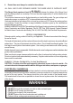
READ AND SAVE THESE INSTRUCTIONS BEFORE YOU START INSTALLING THIS RANGE HOOD WARNING: - TO REDUCE THE RISK OF A RANGE TOP GREASE FIRE: a) Never leave surface units unattended at high settings. Boilovers cause smoking and greasy spillovers that may ignite. Heat oils slowly on low or medium setting. b)Always turn hood ON when cooking at high heat or when flambeing food (i.e. Crepes Suzette, Cherries Jubilee, Peppercorn Beef Flambé). c) Clean ventilating fans frequently.
4. Ducted fans must always be vented to the outdoors. ALL WALL AND FLOOR OPENINGS WHERE THE RANGE HOOD IS INSTALLED MUST BE SEALED. This Range Hood requires at least 24" of clearance between the bottom of the Range Hood and the cooking surface or countertop. This hood has been approved by UL at this distance from the cooktop. This minimum clearance may be higher depending on local building codes. For gas cooktops and combination ranges, a minimum of 30" is recommended and may be required.
ELECTRICAL REQUIREMENTS A 120 volt, 60 Hz AC-only electrical supply is required on a separate 15 amp fused circuit. A time-delay fuse or circuit breaker is recommended. The fuse must be sized per local codes in accordance with the electrical rating of this unit as specified on the serial/rating plate located inside the unit near the field wiring compartment. ! WARNING • Electrical ground is required on this Range Hood.
RANGE HOOD DIMENSIONS 28" 47 " 5
INSTALLATION HEIGHT REQUIREMENTS MIN. 24" OVER ELECTRIC 6 MIN.
MAIN PARTS Ref. 1 8 10 11 Ref. 12a 12b 12e Qty. 1 1 2 1 Qty. 10 4 2 Qty. 1 H H Components Product Components Hood Body, complete with: Controls, Light, Filters,Blower.
Parts needed - 6" Round Metal ductwork .
LINER DIMENSIONS SIDE VIEW / LA PERSPECTIVE DE CÔTÉ Standard Liner 30 Stainless (LINE30ST)designed for 30” wide installations LINER DIMENSIONS / DIMENSIONS DU CADRE TIVE DE FRONT Standard Liner 30 Stainless (LINE30ST) designed for 30” wide installations Cadre Standard 30 Axier Inoxydable (LINE30ST) peut être employée les hottes encastrable sur mesure de 30" LINER DIMENSIONS / DIMENSIONS DU CADRE Standard Liner 36 Stainless (LINE36ST) designed for 36” wide installations Cadre Standard 36 Axier Inoxydable
• Metal Snips • Measuring Tape or Ruler • Level • Pencil • Caulking Gun • Duct Tape • 2 Conduit Connectors • Power Supply Cable • Scews for Field Wiring Box • 1 Wall or Roof Cap • All Metal Ductwork perimeter around the Inca Smart. Depth adjustable from 16" - 17 7/8". Standard Liner 30 Stainless - part # LINE30ST Standard Liner 36 Stainless - part # LINE36ST FOR INSTALLATION WITH LINERS PLAN YOUR DUCTWORK The Inca Smart requires 5" round ductwork.
Choose your ducting method Ducted Venting Installation Non Ducted - Recirculation Requires purchase of Activated Charcoal Accessory #Filter1 6" Top Rear Caution: If an elbow is required, do it as far away from the hood's exhaust opening as possible.
INSTALL THE RANGE HOOD 1 Remove grease filters and set aside. 2 12 Remove the bottom of the Range Hood by pulling as shown.
3 The Hood can be installed directly on the underside of the cabinet (minimum 24" for electric ranges and 30" for gas ranges). Create an opening in the bottom of the Cabinet, as shown.
4 Insert the hood until the side supports snap into place. Lock in position by tightening the screws Vf from underneath the hood. Min.9/16" Max 1" 3/16 Vf 5 14 Fasten using the 10 screws 12a provided.
6 Replace the bottom of the Range Hood by 4 screws 12b as shown.
8 CHOOSE YOUR DUCTING METHOD Ducted Venting Installation 10 Non Ducted Recirculation Option Torx Screwdriver 12e 8 Install the 2 Flap 10 included with the Range Hood as shown. 11 Break the 4 pre-cutting pieces and install the Ring 11 included with the Range Hood before connecting to the ductwork. ´ For Non-Ducted Recirculation venting route the ductwork to a location above the hood where the discharge is vented back into the room.
ELECTRICAL INSTALLATION WITH CONNECTION CABLE 9 GROUNDING INSTRUCTIONS This appliance must be grounded. In the event of an electrical short circuit, grounding reduces the risk of electric shock by providing an escape wire for the electric current. This appliance is equipped with a cord having a grounding wire with a grounding plug. The plug must be plugged into an outlet that is properly installed and grounded. WARNING - Improper grounding can result in a risk of electric shock.
10 For Non-Ducted Recirculation Option Attach each charcoal filter to the black grid on each side of the blower. Press the charcoal filter tightly to the black grid on the blower side and rotate the filter clockwise (towards the front of the insert hood) until it locks into place. Turn counterclockwise (towards the back of the insert hood) to remove.
USE AND CARE INFORMATION For Best Results Start the Range Hood several minutes before cooking to develop proper airflow. Allow the Range Hood to operate for several minutes after cooking is complete to clear all smoke and odors from the kitchen. Button Function LED indicator light (L) - indicates current speed with color Green - speed 1 Orange - speed 2 Red - speed 3 Flashing Red - intensive speed Light On/Off Button On/Off switch for the lights.
Cleaning metal grease filters The metal grease filters can be cleaned in hot detergent solution or washed in the dishwasher. They should be cleaned every 2 months use, or more frequently if use is particularly heavy. • Remove the filter, pushing the lever towards the back of the unit and at the same time pulling downward.
Light Bulb Replacement • Remove grease filters and set aside. • Remove the bottom of the Range Hood by 4 screws 12b as shown. 12b • Replace the lamp with a new one of the same type. • Replace the bottom of the Range Hood by 4 screws 12b. • Replace the grease filters. E12 self-ballasted led lamps – listed in accordance with ul 1993/ nmxj-578/1-ance/ csa c22.2 No.
WIRING DIAGRAM LED LAMP 9 INSP28SS400 INSP28SS600 ORG WHT ESZ 3 SPEED 0-1 MOTOR F V2 4 8 7 5 9 CABLE 1 2 3 6 INSERT MC 1 2 3 4 5 6 BLK ORG BRW M8-4V 8 7 9 SIDE 5 3 2 WHT 4 BLU 1 BLK BLU WHT GRY 2 GRY 6 3 L-B BRW BRW WHT BLU PNK WHT Y-G BLU Y-G PNK BLK V1 4 5 2 SPEED 6 0-1 LIGHT N L V4 L V3 7 6 5 4 3 2 1 L-B ORG BLK ORG GRY 8 ORG L-B BRW PNK 60Hz 110-127V N F 1 Y-G Code 991.0601.656 Created by DOLCE CORRADO Creation date 17.Ott.
FABER CONSUMER WARRANTY & SERVICE All Faber products are warranted against any defect in materials or workmanship for the original purchaser for a period of 1 year from the date of original purchase (requires proof of purchase). This warranty covers labor and replacement parts. Faber, at its option, may repair or replace the product or components necessary to restore the product to good working condition.
VEUILLEZ LIRE ET CONSERVER LA PRÉSENTE NOTICE AVANT DE COMMENCER L'INSTALLATION DE LA HOTTE DE CUISINE AVERTISSEMENT : - POUR RÉDUIRE LE RISQUE D'UN FEU DE GRAISSE SUR LA TABLE DE CUISSON : a) Ne laissez jamais sans surveillance les éléments de la surface de cuisson à température élevée. Les bouillonnements excessifs peuvent provoquer de la fumée et les débordements de graisse peuvent s'enflammer. L'huile doit être chauffée lentement, à une température basse ou moyenne.
AVERTISSEMENT - POUR RÉDUIRE LES RISQUES D'INCENDIE, DE CHOC ÉLECTRIQUE OU DE BLESSURE CORPORELLE, RESPECTEZ LES INSTRUCTIONS SUIVANTES : 1. L'installation et le branchement électrique doivent être réalisés par un technicien qualifié et conformément à tous les codes et normes en vigueur, incluant ceux concernant la construction à l'épreuve du feu. 2.
Installation dans les climats froids Le système de ventilation doit prévoir un registre antirefoulement supplémentaire pour réduire le flux d'air froid inverse, ainsi qu'une barrière thermique non métallique pour réduire la conduction des températures extérieures. Le registre doit être installé du côté air froid par rapport à la barrière thermique. La barrière thermique doit être positionnée le plus près que possible de l'endroit où le système de ventilation pénètre dans la partie chauffée de la maison.
DIMENSIONS HOTTE 28" 47 " 27
HAUTEUR REQUISE POUR L’INSTALLATION MIN. 24" AU-DESSUS D’UNE SURFACE ÉLECTRIQUE 28 MIN.
PIÈCES PRINCIPALES Réf. 1 8 10 11 Réf. 12a 12b 12e Qté 1 1 2 1 Qté 10 4 2 Qté 1 H H Composants Composants du produit Bâti de la hotte, avec : Commandes, éclairage, filtres, ventilateur.
- Conduit métallique 6" circulaire Pièces requises Accessoires disponibles Boîtier de connexion directe, no d'article WIREBOX Caisse 30" acier inoxydable, LINE30ST Caisse 36" acier inoxydable, LINE36ST C L M Filtre à charbon actif, no d'article FILTER1 A A D NEW Filtre à charbon actif, no d'article FILTER1LL Deux personnes requises pour l’installation 30 Portez des gants par mesure de sécurité.
DIMENSIONS DE LA CAISSE SIDE VIEW / LA PERSPECTIVE DE CÔTÉ Caisse standard 30 en acier inoxydable (LINE30ST) conçue pour les installations d'une largeur de 30” LINER DIMENSIONS / DIMENSIONS DU CADRE TIVE DE FRONT Standard Liner 30 Stainless (LINE30ST) designed for 30” wide installations Cadre Standard 30 Axier Inoxydable (LINE30ST) peut être employée les hottes encastrable sur mesure de 30" LINER DIMENSIONS / DIMENSIONS DU CADRE Standard Liner 36 Stainless (LINE36ST) designed for 36” wide installations
• Metal Snips • Measuring Tape or Ruler • Level • Pencil • Caulking Gun • Duct Tape • 2 Conduit Connectors • Power Supply Cable • Scews for Field Wiring Box • 1 Wall or Roof Cap • All Metal Ductwork perimeter around the Inca Smart. Depth adjustable from 16" - 17 7/8". Standard Liner 30 Stainless - part # LINE30ST Standard Liner 36 Stainless - part # LINE36ST POUR INSTALLATIONS AVEC CAISSES PLAN YOUR DUCTWORK The Inca Smart requires 5" round ductwork.
Choisissez la méthode de canalisation Installation avec ventilation canalisée 6" Sans canalisation - recyclage Nécessite l'achat de l'accessoire à charbon actif Filter1 Haut Arrière Attention : Si vous devez installer un coude, placez-le le plus loin possible de l’ouverture d’évacuation de la hotte.
INSTALLATION DE LA HOTTE 1 Retirez les filtres à graisse et mettez-les à part. 2 34 Retirez le fond de la hotte en tirant comme illustré.
3 La hotte peut être installée directement en dessous de l’armoire (distance minimale de 24" des surfaces de cuisson électriques et de 30" pour les surfaces de cuisson au gaz). Pratiquez une ouverture sur le fond de l’armoire, comme illustré. 26” ” 1/2 5/8 ” 1/2 10 ” 1/4 10 1/ 2” ” 1/2 26” 5/8 À noter : L’armoire doit être accessible, pour vous permettre d’atteindre le câble de la hotte et le brancher plus tard, après l’installation du produit.
4 Insérez la hotte jusqu'à ce que les appuis latéraux s'enclenchent. Verrouillez en serrant les vis Vf à partir du dessous de la hotte. Min. 9/16" Max 1" 3/16 Vf 5 36 Fixez-la à l’aide des 10 vis 12a fournies.
6 Remettez en place le fond de la hotte à l’aide de 4 vis 12b comme illustré.
8 CHOISIR LA MÉTHODE DE CANALISATION Installation avec ventilation canalisée 10 Option de recyclage sans canalisation Tournevis étoile 12e 8 Installez les 2 volets 10 inclus avec la hotte comme illustré. 11 Brisez les 4 pièces prédécoupées et installez l’anneau 11 inclus avec la hotte, avant de la raccorder aux conduits. ´ Pour la ventilation avec recyclage sans canalisation, dirigez les conduits à un emplacement au-dessus de la hotte où l'air évacué est retourné dans la pièce.
INSTALLATION ÉLECTRIQUE AVEC CÂBLE DE CONNEXION 9 INSTRUCTIONS DE MISE À LA TERRE Cet appareil doit être mis à la terre. La mise à la terre réduit le risque de choc électrique en cas de court-circuit, car elle fournit un fil d'évacuation au courant électrique. Cet appareil est muni d'un cordon présentant un fil de mise à la terre, avec une fiche de mise à la terre. La fiche doit être insérée dans une prise correctement installée et mise à la terre.
10 Pour option sans canalisation, avec recyclage d'air Fixez les filtres à charbon à la grille noire de chaque côté du ventilateur. Pressez fermement le filtre à charbon contre la grille noire de chaque côté du ventilateur et faites tourner le filtre dans le sens des aiguilles d'une montre (vers l'avant de la hotte encastrable) jusqu'à ce qu'il soit verrouillé en place. Faites tourner dans le sens contraire des aiguilles d'une montre (vers l'arrière de la hotte encastrable) pour l'enlever.
INFORMATION RELATIVE À L'UTILISATION ET L'ENTRETIEN Pour de meilleurs résultats Activez la hotte quelques minutes avant de commencer à cuisiner pour créer un flux d'air adéquat. Laissez la hotte fonctionner quelques minutes après avoir fini de cuisiner pour absorber toute la fumée et les odeurs de la cuisine.
Nettoyage des filtres à graisse métalliques Les filtres à graisse métalliques peuvent être lavés dans une solution d'eau chaude savonneuse ou dans le lave-vaisselle. Ils devraient être nettoyés tous les 2 mois d'utilisation, ou plus fréquemment en cas d'utilisation particulièrement intensive. • Retirez le filtre, en poussant simultanément le levier vers l'arrière de l'appareil et en le tirant vers le bas. • Lavez le filtre sans le plier.
Remplacement des ampoules • Retirez les filtres à graisse et mettez-les à part. • Retirez le fond de la hotte avec les 4 vis 12b comme illustré. 12b • Remplacez l'ampoule avec une nouvelle du même type. • Remettez en place le fond la hotte à l’aide de 4 vis 12b. • Remettez en place les filtres à graisse. Ampoules E12 à ballast intégré – répondant à la norme UL 1993/ nmxj-578/1-ance/csa c22.
SCHÉMA DE CÂBLAGE LED LAMP 9 INSP28SS400 INSP28SS600 ORG WHT ESZ 3 SPEED 0-1 MOTOR F V2 4 8 7 5 9 CABLE 1 2 3 6 INSERT MC 1 2 3 4 5 6 BLK ORG BRW M8-4V 8 7 9 SIDE 5 3 2 WHT 4 BLU 1 BLK BLU WHT GRY 2 GRY 6 3 L-B BRW BRW WHT BLU PNK WHT Y-G BLU Y-G PNK BLK V1 4 5 2 SPEED 6 0-1 LIGHT N L V4 L V3 7 6 5 4 3 2 1 L-B ORG BLK ORG GRY 8 ORG L-B BRW PNK 60Hz 110-127V N F 1 Y-G Code 991.0601.656 Created by DOLCE CORRADO Creation date 17.Ott.
FABER CONSUMER WARRANTY & SERVICE All Faber products are warranted against any defect in materials or workmanship for the original purchaser for a period of 1 year from the date of original purchase (requires proof of purchase). This warranty covers labor and replacement parts. Faber, at its option, may repair or replace the product or components necessary to restore the product to good working condition.
LEA Y GUARDE ESTAS INSTRUCCIONES ANTES DE COMENZAR A INSTALAR ESTA CAMPANA EXTRACTORA ADVERTENCIA: - PARA REDUCIR EL RIESGO DE INCENDIO DE GRASA: a) Nunca deje las unidades de superficie desatendidas en ajustes altos. Las ebulliciones causan humo y derrames grasientos que pueden encenderse. Caliente los aceites lentamente en ajustes bajos o medios. b)Siempre encienda la campana cuando cocine a fuego alto o cuando flamee alimentos (por ej. Crepes Suzette, Cherries Jubilee, Peppercorn Beef Flambé).
3. 4. del tubo de humos (chimenea) del equipo que quema combustible para evitar la retrogresión. Siga las directrices del fabricante del equipo de calefacción y las normas de seguridad tales como los publicados por la National Fire Protection Association (NFPA), la American Society for Heating, Refrigeration and Air Conditioning Engineers (ASHRAE) y las autoridades de los códigos locales. Al cortar o perforar la pared o el techo, no dañe el cableado eléctrico ni otros servicios ocultos.
Instalaciones para clima frío Se debe instalar un registro de retrogresión para minimizar el flujo de aire frío hacia atrás y se debe instalar un interruptor térmico no metálico para minimizar la conducción de temperaturas externas como parte del sistema de ventilación. El registro debe estar en el lado del aire frío del interruptor térmico. El interruptor debe estar lo más cerca posible de donde el sistema de ventilación ingrese a la parte calentada de la casa.
DIMENSIONES DE LA CAMPANA EXTRACTORA 28" 47 " 49
REQUISITOS DE ALTURA DE INSTALACIÓN MÍN. 24" SOBRE ELÉCTRICO 50 MÍN.
PARTES PRINCIPALES Ref. 1 8 10 11 Ref. 12a 12b 12e Cdad. 1 1 2 1 Cdad. 10 4 2 Cdad. 1 H H Componentes Componentes del producto Cuerpo de la campana, completo de: Controles, Luz, Filtros, Soplador.
Piezas necesarias - Conducto metálico redondo de 6".
DIMENSIONES DEL FORRO SIDE VIEW / LA PERSPECTIVE DE CÔTÉ Forro estándar de 30 de acero inoxidable (LINE30ST) diseñado para instalaciones anchas de 30" LINER DIMENSIONS / DIMENSIONS DU CADRE TIVE DE FRONT Standard Liner 30 Stainless (LINE30ST) designed for 30” wide installations Cadre Standard 30 Axier Inoxydable (LINE30ST) peut être employée les hottes encastrable sur mesure de 30" LINER DIMENSIONS / DIMENSIONS DU CADRE Standard Liner 36 Stainless (LINE36ST) designed for 36” wide installations Cadre Sta
• Metal Snips • Measuring Tape or Ruler • Level • Pencil • Caulking Gun • Duct Tape perimeter around the Inca Smart. Depth adjustable from 16" - 17 7/8". Standard Liner 30 Stainless - part # LINE30ST Standard Liner 36 Stainless - part # LINE36ST PARA LA INSTALACIÓN CON FORROS PLAN YOUR DUCTWORK ! • 2 Conduit Connectors • Power Supply Cable • Scews for Field Wiring Box • 1 Wall or Roof Cap • All Metal Ductwork The Inca Smart requires 5" round ductwork.
Elija su método de conducción Instalación de ventilación con conducto 6" Sin conducto - Recirculación Requiere compra de accesorio de carbón activado #Filter1 Parte superior Parte trasera Precaución: Si se requiere un codo, hágalo lo más lejos posible de la abertura de escape de la campana.
INSTALE LA CAMPANA EXTRACTORA 1 Retire los filtros de grasa y déjelos a un lado. 2 56 Retire la parte inferior de la campana extractora tirando como se muestra.
3 La campana se puede instalar directamente en la parte inferior del gabinete (mínimo 24 "para cocinas eléctricas y 30" para cocinas de gas). Cree una abertura en la parte inferior del gabinete, como se muestra.
4 Inserte la campana hasta que los soportes laterales encajen en su lugar. Bloquee en posición apretando los tornillos Vf debajo de la campana. Mín. 9/16" Máx. 1" 3/16 Vf 5 58 Sujete usando los 10 tornillos 12a provistos.
6 Vuelva a colocar la parte inferior de la campana extractora con 4 tornillos 12b como se muestra.
8 ELIJA SU MÉTODO DE CONDUCCIÓN Instalación de ventilación con conducto 10 Sin conducto Opción de recirculación Destornillador Torx 12e 8 Instale las 2 aletas 10 incluidas con la campana extractora como se muestra. 11 Rompa las 4 piezas de precorte e instale el anillo 11 incluido con la campana extractora antes de conectarla al conducto.
INSTALACIÓN ELÉCTRICA CON CABLE DE CONEXIÓN 9 INSTRUCCIONES DE CONEXIÓN A TIERRA Este equipo se debe conectar a tierra. En el caso de un cortocircuito eléctrico, la conexión a tierra reduce el riesgo de descarga eléctrica al proporcionar un cable de escape para la corriente eléctrica. Este equipo está provisto de un cable que tiene un cable de conexión a tierra con un enchufe de conexión a tierra. El enchufe debe estar enchufado a un tomacorriente que esté instalado y conectado a tierra correctamente.
10 Para la opción de recirculación sin conducto Fije cada filtro de carbón a la rejilla negra a cada lado del soplador. Presione el filtro de carbón firmemente contra la rejilla negra en el lado del soplador y gire el filtro en sentido horario (hacia la parte delantera de la campana a insertar) hasta que encaje en su lugar. Gire en sentido antihorario (hacia la parte posterior de la campana a insertar) para quitar.
INFORMACIÓN DE USO Y CUIDADO Para mejores resultados Encienda la campana extractora varios minutos antes de cocinar para desarrollar un flujo de aire adecuado. Deje que la campana extractora funcione durante varios minutos después de que se complete la cocción para eliminar todo el humo y los olores de la cocina.
Limpieza de los filtros de grasa metálicos Los filtros de grasa metálicos se pueden limpiar en solución de detergente caliente o lavarse en el lavavajillas. Se deben limpiar cada 2 meses de uso, o más frecuentemente si el uso es particularmente pesado. • Retire el filtro, empujando la palanca hacia la parte posterior de la unidad y al mismo tiempo tirando hacia abajo.
Reemplazo de la bombilla • Retire los filtros de grasa y déjelos a un lado. • Retire la parte inferior de la campana extractora con 4 tornillos 12b como se muestra. 12b • Reemplace la bombilla con una nueva del mismo tipo. • Vuelva a colocar la parte inferior de la campana extractora con 4 tornillos 12b. • Reemplace los filtros de grasa. Lámparas led autobalastradas E12 - homologadas de acuerdo con ul 1993/nmxj-578/1-ance/ csa c22.2 No.
DIAGRAMA DE CABLEADO LED LAMP 9 INSP28SS400 INSP28SS600 ORG WHT ESZ 3 SPEED 0-1 MOTOR F V2 4 8 7 5 9 CABLE 1 2 3 6 INSERT MC 1 2 3 4 5 6 BLK ORG BRW M8-4V 8 7 9 SIDE 5 3 2 WHT 4 BLU 1 BLK BLU WHT GRY 2 GRY 6 3 L-B BRW BRW WHT BLU PNK WHT Y-G BLU Y-G PNK BLK V1 4 5 2 SPEED 6 0-1 LIGHT N L V4 L V3 7 6 5 4 3 2 1 L-B ORG BLK ORG GRY 8 ORG L-B BRW PNK 60Hz 110-127V N F 1 Y-G Code 991.0601.656 Created by DOLCE CORRADO Creation date 17.Ott.
Esta garantia Aplica para USA y Canada GARANTÍA Y SERVICIO AL CONSUMIDOR FABER FABER CONSUMER WARRANTY & SERVICE Todos losproducts productos están garantizados contra cualquier defecto de materiales o mano de obra para el All Faber areFaber warranted against any defect in materials or workmanship for the original purchaser comprador original por un período de 1 año a partir de la fecha de compra original (requiere prueba de compra).
991.0601.