Operation/ Maintenance Dual Platform Counting Scale WITH OMEGA SERIES COUNTING SCALE MODEL 1129 SERIES © 2012 by Fairbanks Scales, Inc.
Amendment Record Dual Platform Counting Scale With Omega Series Counting Scale Model 1129 Series Document 51300 Manufactured by Fairbanks Scales Inc. 821 Locust Kansas City, Missouri 64106 08/12 Created 07/12 Revision 1 08/12 Released Product 3 51300 Rev.
Disclaimer Every effort has been made to provide complete and accurate information in this manual. However, although this manual may include a specifically identified warranty notice for the product, Fairbanks Scales makes no representations or warranties with respect to the contents of this manual, and reserves the right to make changes to this manual without notice when and as improvements are made.
Table of Contents SECTION 1: GENERAL INFORMATION .................................................................. 7 1.1. Introduction.............................................................................................................. 7 1.1.1. 1.2. Description .............................................................................................................. 8 1.2.1. 1.2.2. 1.3. Omega Series Scales .................................................................................
Table of Contents SECTION 4: USER OPERATIONS .......................................................................... 18 4.7. More operations..................................................................................................... 33 4.7.1. 4.7.2. 4.7.3 4.8. Accumulation .................................................................................................................. 33 Recall ................................................................................................
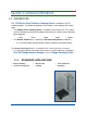
Section 1: General Information 1.1. INTRODUCTION The 1129 Series Dual Platform Counting Scale is available in five (5) standard models. The difference between these models is the capacity of the local scale. The Omega Series Counting Scale is available in five model sizes. This allows the user to weigh and count their products based on the smallest size of the parts being weighed. – 6 lbs. – 15 lbs. – 30 lbs. – 60 lbs. – 100 lbs.
Section 1: General Information 1.2. DESCRIPTION 1.2.1. Omega Series Scales The self-contained, local weighing platform and instrument, Omega Counting Scale is designed in a rugged ABS plastic enclosure with a stainless steel weighing platform, perfect for almost any counting scale application. – The 9.64” x 13.97” weighing platform can easily accommodate most parts counting needs. Standard units include the following features.
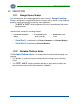
Section 1: General Information 1.3. TECHNICAL SPECIFICATIONS 1.3.1. Omega Series Basic Specification DIGITAL DISPLAY LCD, height 0.6 in (14.5 mm) 6/7/7(Weight / Piece Weight / Total Pieces) PLATTER SIZE 9.64” x 13.97” (245 x 355 mm) DIMENSIONS (15.24” x 14.37” x 4.61” (387 x 365 x 117 mm) NET WEIGHT (KG) 8.16 lbs. (3.
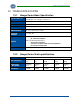
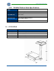
Section 1: General Information 1.3.3. Portable Platform Scale Specifications MODEL Portable Platform Scale MAXIMUM CAPACITY 1000 lbs/ 454 kgs DIVISION SIZE (D) 0.5 lbs/ 0.2 kgs PLATFORM SIZE 17.75” x 23.5” OVERALL LENGTH 37” CONSTRUCTION Base/ Platform/ Wheels: Cast Iron Column: Fabricated Steel WEIGHT 168 lbs/ 76 kgs 1.4. ACCESSORIES PRODUCT NO. 08/12 DESCRIPTION 31701 Bar code scanner (Symbol) with hands-free stand 31789 Dust cover (Qty.
Section 2: Customer Service Information 2.1. GENERAL SERVICE POLICY It is the customer/operator's responsibility to ensure the equipment provided by Fairbanks is operated within the parameters of the equipment's specifications and protected from accidental or malicious damage.
Section 2: Customer Service Information IMPORTANT INSTALLATION NOTICE All load cells, load cell cables and interconnecting cables used to connect all scale components shall be located a minimum of thirty-six (36”) inches distance away from all single and multiple phase high energy circuits and electric current carrying conductors. This includes digital weight indicators, junction boxes, and power supplies.
Section 3: Installation 3.1. TOOLS REQUIRED #1 or Small Slotted Screwdriver #2 Phillips Screwdriver 10" Adjustable Wrench Pliers 3.2. WHEEL AND PILLAR ASSEMBLY 6. Set the Scale Base Assembly (#4) sideways on the floor. 7. Insert a Cotter Pin (#17) through the small hole in one end of the First Axle (#19). 8. Place a Flat Washer (#18) and a Wheel (#16) onto the open end of the axle. 9. Insert the axle's other end through both holes in the base. 10. Place the Second Wheel (#16) onto the axle.
Section 3: Assembly 3.2. WHEEL & PILLAR ASSEMBLY, CONTINUED 16. With the Scale Base Assembly (#4) in an upright position Screw the two (2) Pillar Rods (#1) into the two (2) tapped holes of the base. 17. Place the Pillar (#2) over the pillar rods. – The cutouts face to the left and right of the platform 18. Insert the Steelyard Rod (#35) down through the pillar. – The bent hook is on top, and the loose swivel hook is on the bottom. 08/12 14 51300 Rev.
Section 3: Assembly 3.3. MOUNTING BRACKET KIT ASSEMBLY NOTE: The MOUNTING BRACKET KIT ASSEMBLY is partially assembled. 1. With the portable platform right-side-up, place the Bracket (#7) on top of the pillar. – The two (2) pillar rods must pass through the two (2) holes in the Bracket (#7). – The scale display may face any direction on the platform. 2. Place the Stiffener Plate (#8) on the pillar rod, inside the bracket. 3.
Section 3: Assembly 3.3. MOUNTING BRACKET KIT ASSEMBLY, CONTINUED 9. Place the two (2) washers on the Pillar Bolts, install the nuts on the Pillar Bolts, then tighten the nuts to pull the whole assembly together. 10. On the bottom back-side of the scale’s base, lift up the Lever End (#34) while placing the hook under the lever's pivot. – Do this while holding the top of the Beam Load Rod assembly. 11. Insert the “S” Hook (#3) into the eye on the end of the Load Cell Linkage Cable Assembly (A).
Section 3: Assembly 3.4. INSTALLING THE INSTRUMENT 1. Remove the four (4) feet from the bottom of the Omega Counting Scale. 2. Place the scale on the bracket with the front of the scale oriented in the most useful direction. 3. Re-install the feet through the holes in the bracket, into the bottom of the counting scale. 4. Plug the Load Cell Cable Connector into the Remote Scale Port on the side panel of the counting scale. 08/12 17 51300 Rev.
Section 4: User Operations 4.1. INTRODUCTION The Omega Series Counting Scale is a weighing device that displays the number of similar items in a group based upon the weight of a known sample. – The counting feature of this scale calculates the average piece weight for the items by using the total weight of the sample and dividing that number by the number of items in the sample.
Section 4: User Operations 4.2 FRONT PANEL DISPLAY AND KEY FUNCTIONS 4.2.1. LCD Display Definitions 1 Actual weight display. 2 Second row displays Piece Weight. Also used as keypad input display 3 The third row displays Piece Counts, and abbreviated as PCS. 4 Indicates the battery power is low. A battery recharge or battery replacement is required for further operation. 5 Indicates the first row displays the Net weight after Tare Operation. 6 Indicates the weight is stable.
Section 4: User Operations 4.2.2. Keypad Functions Key Function Turns the scale OFF. Turns the scale ON. Initiates a PRINT cycle. • Internal Programming must be activated. Confirms the entry or selection. ~ Press the numeric and decimal keys to input data such as piece weight, PLU no., etc. Changes the Unit of Measure. • • Pound (lb) or Kilogram (kg). The current unit selected is displayed on the right hand side of the actual weight display. Sets the scale to ZERO.
Section 4: User Operations 4.2.2. Keypad Functions, Continued KEY FUNCTION Adds a piece count and weight. Switches operation between Scale A (main scale) and Scale B (remote scale). Stores, loads, or modifies a preset piece weight. PLU (Part Look Up) keys. Loads preset piece weight data from the nine (9) PLU keys. RECALLS total piece count and total weight. Press to set up SAMPLE quantity. (Sample key: multiple sampling methods are available. (See Sampling.) Sets up PIECE WEIGHT.
Section 4: User Operations 4.3. BASIC OPERATIONAL FUNCTIONS NET 4.3.1. Gross, Tare and Net Weight There are three terms used when weighing a product. The NET WEIGHT (product only) is the GROSS WEIGHT (total amount) minus the TARE WEIGHT (container only). NET WEIGHT = Gross Weight – Tare Weight G R O S S T A R E WORKING EXAMPLE A full can of house paint is an object to be weighed. The empty can is the TARE weight. The paint is the NET weight.
Section 4: User Operations 4.3.2. Counting by Piece Weight The Omega Counting Scale counts items by their Piece Weight. – If the weight of each item is known, the items are counted based upon the weight upon the scale. A WORKING EXAMPLE There are ten (10) pounds of bolts on a scale. Each bolt weighs a tenth of a pound (0.10 lbs.) The scale performs an internal calculation and displays one hundred (100) on the third PIECES line on the display. There are two ways to set the Piece Weight. Keypad input.
Section 4: User Operations 4.4.2. Manual Tare Entry Using The Keypad 1. While in the Weigh Mode, input the Tare Weight using the numeric keys – If the unit indicated is kg, the tare entry is in kilograms. – If the unit indicated is lb, the tare entry is in pounds. 2. Press , and the tare weight has been stored. – The Tare data clears in ten (10) seconds if – is not pressed. is displayed. EXAMPLE 1. Press to manually enter the tare weight as 0.5 lb. 2. Press the key. is displayed.
Section 4: User Operations 4.5.2. Setup Piece Weight By Sampling (Quick Set) 1. While in the Weigh Mode, place items to be weighed onto the scale pan. 2. While in the Weigh Mode, manually input the Piece Count using the keypad. 3. Press to calculate – The Piece Weight data will be cleared in ten (10) seconds if the not pressed. 4. Press key is to clear the Piece Weight amount. EXAMPLE 1. Place a one pound (1 lb) test weight on the scale weighing pan. 2. Press to set this as the number of pieces.
Section 4: User Operations 4.5.3. Setup Piece Weight by Sampling (Place Item) Set the Piece Weight on ZERO. 1. – The scale will calculate the Piece Weight Value by what is added and Piece Count Number, as described below. 2. Press the key. – The second row of LCD displays . – The third row displays a default value of 100. 3. Enter the new sampling quantity using the keypad. 4. Place the items to be weighed onto the scale pan. – Wait five (5) seconds for the weight to stabilize.
Section 4: User Operations 4.5.4. Setup Piece Weight By Sampling (Remove Item) 1. Set the Piece Weight on ZERO. 2. Place a item on the weighing pan. – The scale will calculate the Piece Weight Value by the change in weight. 3. Press . – The second row of LCD displays . – The third row of LCD displays the default value as 100. 4. Press the numeric keys to enter the new sampling quantity. 5. Remove the items to obtain the desired piece counts value from the weighing pan.
Section 4: User Operations 4.5.5. Setup Piece Weight by Sampling (Re-sample) If the Piece Weight and Total Weight have not been cleared, weight can be added or removed, then the key can be pressed to calculate the piece weight again. EXAMPLE 1. Place a one pound (1 lb) test weight on the scale weighing pan. 2. Press to set this as the number of Pieces. – It displays on the second line. 3. Press . – Displays the Piece Weight on the second line. – Displays the Piece Count on the third line. 4.
Section 4: User Operations 4.6. PLU (PART LOOK UP) OPERATION PLU (Part Look Up) is a memory lookup number that includes the Piece Weight and Tare Weight. – The scale can store up to 999 PLU items into memory. – When any PLU is activated, the scale replaces the current Piece Weight and Tare Weight with the PLU selected from memory. 4.6.1. Setting Up PLU Keys 1 thru 9 1. Set up Piece Weight as described in Section 4.5. Sampling Operation. 2. Press . – flashes on the display. 3.
Section 4: User Operations 4.6.2. Setting Up PLU Keys 0 thru 999 1. Set up the Piece Weight as in Section 4.5. Sampling Operation. 2. Press and will flash on the display. 3. Press the numeric keys to select PLU number, with a three (3) digit maximum. 4. Press to save your setting, will stop flashing on the display. 5. If the entry needs to be cleared press the key. EXAMPLE 1. Press 2. Press – + to enter a Piece Weight as 0.5 pounds. . flashes on the display. 3. Press key.
Section 4: User Operations 4.6.3. Loading PLU 1 thru 9 1. In the Weight Mode, press any of the Direct PLU keys to access the PLU memory of the key’s lower-right set. 2. In the case of pressing this PLU 3 key ( – The LCD shows 3 below the ), this function will load. indicator. NOTE: If there is no data input in thirty (30) seconds, scale exits the PLU Setting Mode and returns to Weight Mode. 4.6.4. Loading PLU 0 thru 999 1. While in the Weight Mode, press and hold it.
Section 4: User Operations 4.6.5. Modifying a PLU 1. When displays, press . – The Piece Weight flashes. 2. Set up PIECE WEIGHT according to the previous section. 3. Press to save your settings. EXAMPLE 1. Press key to access the third PLU. 2. Press key to access the PLU modify mode. 3. The Piece Weight flashes. 4. Press the keys. – The Piece Weight is 0.5. 5. Press key to complete the PLU Modifying Process. – The Tare Weight blinks. 6. Enter the new TARE WEIGHT. 7.
Section 4: User Operations 4.7. MORE OPERATIONS 4.7.1. Accumulation 1. When there is a load on the scale weighing pan and piece weight has been input. 2. Press . – When the indicator beeps, has been recorded. lights up on the LCD, indicating a data 3. Clear the load and put another load on the scale weighing pan. Set up the piece weight again. 4. Press . 5. The indicator beeps, recorded. lights up, and the Indicating Second Data is Example: 1. Empty the scale weighing pan. – The weight must be 0.
Section 4: User Operations 4.7.2. Recall TOTAL MODE 1. In weighing mode, press and the Weight column will be cleared. – The Piece Weight column displays . 2. The PCS column shows the total piece count in memory. – The Weight column shows the accumulated weight. 3. The number above “ACC” indicator is the record size. 4. Press to exit without clearing the data. 5. Press to clear the data and exit. EXAMPLE 1. Clear scale weighing pan. Make sure the weight is 0.
Section 4: User Operations 4.7.2. Recall, Continued RECORD VIEW MODE 1. Enter the Total Mode. 2. Press to enter record view mode. 3. Toggle through each of the stored accumulation records in memory by pressing the . – If current record is the last record, it will return to total mode. – The number shown above the “ACC” indicates the number of current record. Weight, Piece Weight and Piece is the data of current record. 4. Press to return to the Weight Mode. 5. Press to clear current record.
Section 4: User Operations 4.7.2. Recall, Continued EXAMPLE, Continued 11. Press to switch to the second record. – It is the last record. 12. Press to return to the Total Mode. 13. Press to access Record View Mode again. 14. Press to return to normal weigh mode. – The ACC data is still in memory, and is illuminated. 15. Press twice to access the Record View again. 16. Press key to clear the first record. – The display shows the next record. – The first is removed.
Section 4: User Operations 4.7.3 Alarm Function PIECE ALARM 1. Press . – The PCS column displays . – The piece weight column shows the PCS Upper Limit setting. 2. Configure the PCS Upper Limit with the numeric keys. 3. Press again. – The PCS column displays . 4. Configure the PCS Lower Limit settings with the numeric keys. 5. Press Mode. to save the Piece Lower Limit Value and to enter the Weight Alarm EXAMPLE 1. Press key to enter the Piece Upper Limit setting. – The PCS column displays .
Section 4: User Operations 1.7.3 Alarm Function, Continued EXAMPLE, Continued 8. Place eleven pounds (11 lbs.) on scale weighing pan. – The Piece Weight shows twenty-two pounds (22 lbs.) – The Upper Limit Alarm displays and will be flashing. – An audible alarm will start if the High Beep Sound is enabled. WEIGHT ALARM After configuring the Piece alarm, the scale enters the Weight Alarm setting. – The PCS column displays . 1. Set up the Weight Lower Limit with the numeric keys.
Section 4: User Operations 4.7.3. Alarm Function, Continued EXAMPLE, Continued 6. Put one pound (1 lb.) on scale weighing pan. – The Lower Alarm is indicated and flashing – An audible alarm will start if the Low Beep Sound is enabled. 7. Put eleven pounds (11) on scale weighing pan. – The Upper Limit Alarm displays and will be flashing. – An audible alarm will start if the High Beep Sound is enabled. IMPORTANT NOTES: 1.
Section 5: Service and Maintenance 5.1. BASIC CLEANING The Omega Series Counting Scales may be cleaned with a damp cloth and mild detergent. Do not use chemical cleaners or abrasive type scouring pads. 5.2. TROUBLESHOOTING 5.2.1. Error Code List ERROR DESCRIPTION OL1 Weight on the main scale is larger than the maximum scale capacity. OL2 Weight on the external scale is larger than the maximum scale capacity range. UL1 Weight on the main scale is out of range below the zero reference.
Section 5: Service and Maintenance 5.2.2. Solutions SYMPTOM “UL1” or “UL2” “OL1” or “OL2” Does not return to “0.0” “Error3” CAUSE • • • • • • • Bind • Blank display “LoBAtt” • Below ZERO Bind Over Capacity Bind Possible damaged load cell. Possible A/D failure. • • SOLUTION Bind Possible damaged load cell. Possible A/D failure. • • • Battery pack discharged.
Section 6: Parts 6.1. PLATFORM AND PILLAR ASSEMBLY PARTS LIST ITEM PART NO.
Section 6: Parts 6.2. PLATFORM & PILLAR ASSEMBLY DIAGRAM 08/12 43 51300 Rev.
Section 6: Parts 6.3. ACC 380 MOUNTING BRACKET PARTS ITEM PART NO. 1 14230 Load Cell Assembly (90 lb Cap load cell 13199) 2 22706 Cable Assembly 3 12643 “S” hook 5 11263 Cable Clip 7 20176 Bracket 8 14237 Stiffener plate --- 13099 Cable Linkage 08/12 DESCRIPTION 44 51300 Rev.
Section 6: Parts 6.4. OMEGA SERIES PARTS LIST ITEM PART NO.
Section 6: Parts 6.5. PARTS DIAGRAM 7 6 12 9 1 8 11 4 10 3 2 5 08/12 46 51300 Rev.
Appendix I: Remote Platform Wiring 1 4 2 3 INSTRUMENT CONNECTOR PIN DESCRIPTION 1 + EXC 2 – EXC 3 + SIG 4 – SIG W A R N I N G ! Never perform any wiring with the instrument turned on! Damage to system components can occur. 08/12 47 51300 Rev.
APPENDIX II: RS232C Connection:DB9 (Male) 08/12 PIN DESCRIPTION 1 DCD 2 RX 3 TX 4 DTR 5 GND 6 DSR 7 RTS 8 CTS 9 RI 48 51300 Rev.
OMEGA SERIES COUNTING SCALE Dual Platform Counting Scale Manufactured by Fairbanks Scales, Inc. 821 Locust Street Kansas City, MO 64106 www.fairbanks.