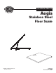
Installation Manual Aegis Stainless Steel Floor Scale © 2007 by Fairbanks Scales Inc.
Amendment Record Aegis Stainless Steel Floor Scale 51103 Manufactured by Fairbanks Scales Inc. 821 Locust Kansas City, Missouri 64106 Revision 0 01/07 Preliminary Release Revision 1 01/07 Manual Release Disclaimer Every effort has been made to provide complete and accurate information in this manual.
Table of Contents Section 1: General Information A. Introduction . . . . . . . . . . . . . . . . . . . . . . . . . . . . . . . . 4 B. Description . . . . . . . . . . . . . . . . . . . . . . . . . . . . . . . . . 4 C.Specification . . . . . . . . . . . . . . . . . . . . . . . . . . . . . . . . 4 Section 2: Installation A. General Service Policy . . . . . . . . . . . . . . . . . . . . . . . B. Overview . . . . . . . . . . . . . . . . . . . . . . . . . . . . . . . . . C. Pre-Installation Checklist . . . . . .
Section 1: General Information A. Introduction: The Aegis Stainless Steel floor scale features a rugged structural rib design and a nominal height of three inches -- among the lowest in the industry. With a full range of accessories, these scales can be configured to fit most floor scale applications. B. Description: The Aegis Industrial Stainless Steel series floor scale platform is fully assembled and pre-wired.
Section 2: Installation A. General Service Policy: Prior to installation, it must be verified that the equipment will satisfy the customer's requirements as supplied, and as described in this manual. If the equipment cannot satisfy the application, and the application cannot be modified to meet the design parameters of the equipment, the installation should not be attempted.
The complete installation consists of: 1. 2. 3. 4. Verifying the application Unpacking Floor scale checkout Customer and site readiness: a. Is the Location ready? b. Is the customer aware there may be work disruptions? c. Are the operators available for training? 5. Floor scale connections 6. Adjustments 7. Customer training NOTE: It is the owner’s responsibility to document, notify, and follow-up with the carrier if there is shipping damage.
D. Unpacking: 1. Check that all components are on hand, and agree with the customer's order. 2. Remove all components from their packing material, checking to make certain that all parts are accounted for and no parts are damaged. Advise the shipper immediately if damage has occurred. Order any parts necessary to replace those which have been damaged. Keep the shipping container and packing material for future use. Check the packing list. 3. Collect all necessary installation manuals for the floor scale.
3. Screw two (2) eyebolts into the threaded adapters in the platform top and use a forklift or other lifting means along with chains, cables, or nylon straps to remove the scale from the crate. CAUTION: Do NOT use grab or slip hooks to lift the scale. Failure to use the proper lifting tools may result in personal injury. 4. Set the scale so that the interface cable exits in a direction where it can be protected.
ii. Intalogix™ Technology Interface (QMB 15291): QMB Terminal 1 2 3 4 5 6 7 8 9 10 Wire Color Green Red Black White Brown Blue Orange Yellow Violet Gray/Shield Intalogix™ Technology Inst 1 2 3 4 5 6 7 8 9 10 Function (-) Excitation (+) Excitation Ground D out D In EOC SCLK CS Temperature Chassis NOTE: 1. If the Gray/Shield wire is equipped with a screw lug, it can be attached using one of the PCB screws. 2. Calibrate the Intalogix™ platform / indicator.
c. Cornering the scale: Place a load which is 25% of platform capacity upon the scale at the corner 1 location. Note the indication. Proceed to each successive corner with the weight and note each indication. If corners require adjustment, place the load on the corner displaying the lowest weight and use the appropriate potentiometer to change the displayed weight to read the same as the highest reading by turning the potentiometer clockwise (CW).
Section 3: Accessories Installation Bolt-down plates, ramps, bumper guards, and pit frames are installed as follows: A. Bolt-Down Plates: Bolt down plates are used to keep the scale from sliding or moving when loads are applied. The plates are bolted via anchors at each of the scale's feet. Installation: 1. Place the platform in position. 2. Place the bolt-down plate under the foot, plate edge extending out from under the scale. 3. Drill the two holes using a hammer drill.
2. Drill holes using a hammer drill or its equivilent. Clean the hole thoroughly. Insert the anchor(s) with the nut and washer in place. Tap the anchor(s) into the hole(s) and tighten the nuts securely. D. Pit Frames: The pit frame accessory is a one-piece welded unit with no additional welding required. This accessory is designed for in-floor applications. In general, a hole is cut in the concrete, the pit frame accessory is installed in the hole, then concrete is poured around and under the frame.
Wire 2x4 Frame Assy Pit 50604-2 • Use the drawing in Appendix III for measurements, concrete specifications and amounts. • Make sure the conduit for the scale cable is in place and secured into the frame opening. • Pour the concrete around and under the frame ensuring a smooth and level finish. • If a drain is required, form the pit to provide a slope in the pit floor to the drain. Refer to the drawings in the Appendix. • Cure to a minimum of 2000 psi before cutting wire.
Section 4: Maintenance and Service A. Load Cell Replacement: 1. Remove power to the indicator. 2. Remove the platform access cover then the junction box cover and disconnect the failed load cell cable at the junction box. Loosen the gland bushing and tie a string or wire to the end of the cable to act as a pull wire. (Check that all cells have wire markers on the cable ends. If not, identify cells with wire markers or other means). 3. Lift the platform end and secure using wood blocks for safety. 4.
10. Load Cell Specifications: Specifications Material: Resistance: Rated Output: Safe Overload: Compensated Temp range: Safe Operating Temp range: B. Stainless Steel Stainless Steel 17-4ph 1000 Ohm 2 mV/V 150% -10ºC to 40ºC -18ºC to 65ºC Analog Junction Box and Optional QMB PCB Replacement: 1. Remove power to the indicator. 2. Open the platform access cover, then the box cover. 3. Loosen all gland bushing nuts. 4. Check that all load cells have wire markers on the cable ends.
C. Foot Assembly Replacement: 1. Lift the platform end and secure using wood blocks for safety. 2. Remove the bolt which goes through the load cell and post of the foot. 3. Pull the foot assembly out of the load cell. 4. Lubricate the “O” ring on the new foot assembly and re-insert the post of the new assembly into the load cell. 5. Align the bolt hole in the part with the bolt hole in the load cell. 6. Install the bolt and tighten. 7. Removing the safety blocks, lower the scale to the surface. 8.
Section 5: Parts A. Stainless Steel Platforms Item Part# Models 1 2 2 2 3 4 5 6 See Appendix I Platform Weldment 63895 Load Cell, 1K LCF HR 4060-2 63896 Load Cell, 2.5K LCF HR 4060-3 63897 Load Cell, 5K LCF HR 4060-4 66754 Load Cell Shim 63899 Foot Assembly 54503 Load Cell Mtg Bolt ½'-20 x 1 ¾" 67171 Analog Junction box See Appendix I 1K, 2.
Parts Diagram - Stainless Steel Models 3 2 5 4 2 15/16" Ref Section of Load Cell 1 Corner No. 3 Corner No. 2 AEGIS TM Corner No. 4 9 Corner No. 1 6 15 16 14 3 11 12 17 7 Bottom View 8 FAIRBANKS SCALES 51103 10 Serial Plate 18 01/07 -- Rev.
B. Stainless Steel Lift Deck Platforms: Item Part# Description Models 1 2 2 2 3 4 5 * * * * See Appendix I Platform Weldment 23426 Load Cell, 1K 23427 Load Cell, 2.5K 23428 Load Cell, 5K 66754 Load Cell Shim 63899 Foot Assembly 54503 Load Cell Mtg Bolt ½'-20 x 1 ¾" 67171 Analog Junction Box 96141 PCB for Analog box 23902 J-Box, Remote Cradle Bracket 15291 QMB Junction Box (optional) See Appendix I 1K, 2.
Parts Diagram - Stainless Steel Lift Deck 3’ x 3’ and 4’ x 4’ Models C4 C3 LOCATE ON UNDERSIDE OF DECK INTERLOCK WIRE TIES TO HOLD CABLES TO ANGLE C1 C2 BOTTOM VIEW OF SCALE CORNER 1 DETAIL "A" CORNER 2 3.10 REF LOCATE THESE LABELS ON BASE FRAME ASSY TUBE SEE DETAIL "A" 13. CORNER 3 CORNER 4 TOP VIEW OF SCALE 15. NOTES: 1. APPLY ANTI-SEIZE SEALING COMPOUND TO BOLT THE LOAD CELLS TO THE MOUNTING BLOCKS. TORQUE TO 90 FT-LB. 2.
Parts Diagram - Stainless Steel Lift Deck 5’ x 5’ Models C3 HINGE SIDE C4 LOCATE ON UNDERSIDE OF DECK INTERLOCK WIRE TIES TO HOLD CABLES TO ANGLE C1 C2 DETAIL "A" BOTTOM VIEW OF SCALE CORNER 1 CORNER 2 3.10 REF LOCATE THESE LABELS ON BASE FRAME ASSY TUBE SEE DETAIL "A" 13. CORNER 4 15. CORNER 3 TOP VIEW OF SCALE NOTES: 1. APPLY ANTI-SEIZE SEALING COMPOUND TO BOLT THE LOAD CELLS TO THE MOUNTING BLOCKS. TORQUE TO 90 FT-LB. 2.
Appendix I: Model Matrix A.
Appendix II: Accessories A. Stainless Steel Ramps, Bumper Guards and Pit Frames: Bumper Pit Size Cap Ramp Guard Frame 30" 1K 64059 (30") 3' x 3' 1K 63752 (3') 72199 (3') 63758 3' x 3' 2.5K 63752 (3') 72199 (3') 63758 4' x 4' 2.5K 63754 (4') 72195 (4') 63760 4' x 4' 5K 63754 (4') 72195 (4') 63760 4' x 4' 10K 63754 (4') 72195 (4') 63760 4' x 5' 5K 63754 (4') 72191 (5') 63762 4' x 5' 10K 63754 (4') 72191 (5') 63762 4' x 6' 5K 63754 (4') 72197 (6') 63764 4' x 6' 10K 63754 (4') 72197 (6') 63764 5' x 5' 2.
50604-9 Appendix III: Standard Pit Frame and Installation Drawing 51103 24 01/07 -- Rev.
Appendix IV: Lift Deck Pit Frame Installation Drawing 51103 25 01/07 -- Rev.
Fairbanks Scales This page intentionally left blank. 51103 26 01/07 -- Rev.