
Instruction Manual

Section 3: Installing the Instrument and Plug-In Cards
10/08 19 51207 Revision 1
3 Installing the Instrument and Plug-in Cards
Before starting work, please read Chapter 1 and follow all instructions.
Further procedures:
• Check the consignment: unpack the components specific to the application.
• Safety check: inspect all components for damage.
• Make sure the on-site installation is correct and complete including cables, e.g. power cable fuse
protection, load cells, cable junction box, data cable, console/cabinet, etc.
• Follow the instructions for installation of the unit relating to application, safety, ventilation, sealing
and environmental influences).
• If necessary, mount the plug-in cards (instrument must be disconnected from all voltage
sources).
• Connect the cable from cable junction box or platform/load cell.
• If applicable: connect other data cables, power cable, etc.
• Connect the instrument power cable.
• Check the installation.
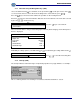
3.1 MECHANICAL PREPARATION
For cabinet or panel mounting, a corresponding cut-out for the housing must be provided (see
Chapter 2.2).
Have all required parts, technical documents and tools at hand for mounting. Secure the cable at
the place of installation; e.g., using cable ties. Remove the insulation from the cable ends, keep the
strands short and fit them with ferrules.
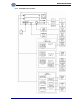
3.2 HARDWARE CONSTRUCTION
The electronics are contained on two printed circuit boards: the main board and the display board.
The display board is connected to the main board by a plug.
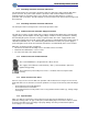
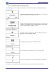
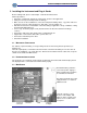
3.3 MAIN BOARD
The lithium battery (under the
cover for the power supply) is
always activated and energizes
the calendar/clock module.
The main board holds the power
supply and Slots 1, 2 and 4 for
additional cards.
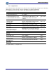
Load cell connector, serial
interface, LAN adaptor, CAL
switch as well as 3 inputs and
outputs are accessible on the
back panel.
Load cell
connector
RS-232
LAN
CAL
3 inputs
3 outputs