
Datasheet


© 2009 Fairchild Semiconductor Corporation www.fairchildsemi.com
FAN2106 • Rev. 1.1.2 12
FAN2106 — TinyBuck™ 3-24V Input, 6A, High-Efficiency, Integrated Synchronous Buck Regulator
Setting the Ramp Resistor Value
R
RAMP
resistor plays a critical role in the design by
providing charging current to the internal ramp capacitor
and also serving as a means to provide input voltage
feedforward.
R
RAMP
is calculated by the following formula:
2
10)18(
)8.1(
6
)(
−
•••
•−
=
−
Ω
fV
VV
R
IN
OUTIN
KRAMP
(5)
where frequency (f) is expressed in KHz.
For wide input operation, first calculate R
RAMP
for the
minimum and maximum input voltage conditions and
use larger of the two values calculated.
In all applications, current through the R
RAMP
pin must
be greater than 10 µA from the equation below for
proper operation:
A
R
V
RAMP
IN
μ
10
2
8.1
≥
+
−
(6)
If the calculated R
RAMP
values in Equation (5) result in a
current less than 10
µA, use the R
RAMP
value that
satisfies Equation (6). In applications with large input
ripple voltage, the R
RAMP
resistor should be adequately
decoupled from the input voltage to minimize ripple on
the RAMP pin
.
Setting the Current Limit
The current limit system involves two comparators. The
MAX I
LIMIT
comparator is used with a V
ILIM
fixed-voltage
reference and represents the maximum current limit
allowable. This reference voltage is temperature
compensated to reflect the R
DSON
variation of the low-
side MOSFET. The ADJUST I
LIMIT
comparator is used
where the current limit needs to be set lower than the
V
ILIM
fixed reference. The 10 µA current source does not
track the R
DSON
changes over temperature, so change is
added into the equations for calculating the ADJUST
I
LIMIT
comparator reference voltage, as is shown below.
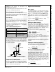
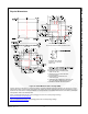
Figure 24 shows a simplified schematic of the over-
current system.
Figure 24. Current-Limit System Schematic
Since the I
LIM
voltage is set by a 10 µA current source
into the R
ILIM
resistor, the basic equation for setting the
reference voltage is:
V
RILIM
= 10µA*R
ILIM
(7)
To calculate R
ILIM
:
R
ILIM
= V
RILIM
/ 10µA (8)
The voltage V
RILIM
is made up of two components, V
BOT
(which relates to the current through the low-side
MOSFET) and V
RMPEAK
(which relates to the peak
current through the inductor). Combining those two
voltage terms results in:
R
ILIM
= (V
BOT
+ V
RMPEAK
)/ 10µA (9)
R
ILIM
= {0.96 + (I
LOAD
* R
DSON
*K
T
*8)} +
{D*(V
IN
– 1.8)/(f
SW
*0.03*R
RAMP
)}/10µA
(10)
where:
V
BOT
= 0.96 + (I
LOAD
* R
DSON
*K
T
*8);
V
RMPEAK
= D*(V
IN
– 1.8)/(f
SW
*0.03*R
RAMP
);
I
LOAD
= the desired maximum load current;
R
DSON
= the nominal R
DSON
of the low-side MOSFET;
K
T
= the normalized temperature coefficient for the
low-side MOSFET (on datasheet graph);
D = V
OUT
/V
IN
duty cycle;
f
SW
= Clock frequency in kHz; and
R
RAMP
= chosen ramp resistor value in kΩ.
After 16 consecutive, pulse-by-pulse, current-limit
cycles, the fault latch is set and the regulator shuts
down. Cycling V
CC
or EN restores operation after a
normal soft-start cycle
(refer to the Auto-Restart
section)
.
The over-current protection fault latch is active during
the soft-start cycle. Use 1% resistor for R
ILIM
.
+
_
V
CC
1
0µA
ILIMIT
ILIM
RILIM
+
_
ILIMIT
ADJUST
MAX
+
_
COMP
PWM
VERR
PWM
ILIMTRIP
VILIM
RAMP