
Datasheet


©2004 Fairchild Semiconductor Corporation www.fairchildsemi.com
FOD2743A, FOD2743B, FOD2743C Rev. 1.0.1 12
FOD2743A, FOD2743B, FOD2743C — Optically Isolated Error Amplifier
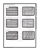
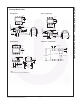
Package Dimensions
Through Hole
Surface Mount
Note:
All dimensions are in inches (millimeters)
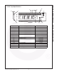
0.4" Lead Spacing
8-Pin DIP – Land Pattern
0.200 (5.08)
0.140 (3.55)
0.100 (2.54) TYP
0.022 (0.56)
0.016 (0.41)
0.020 (0.51) MIN
0.390 (9.91)
0.370 (9.40)
0.270 (6.86)
0.250 (6.35)
3
0.070 (1.78)
0.045 (1.14)
241
56 7
8
0.300 (7.62)
TYP
0.154 (3.90)
0.120 (3.05)
0.016 (0.40)
0.008 (0.20)
15° MAX
PIN 1
ID.
SEATING PLANE
Lead Coplanarity : 0.004 (0.10) MAX
0.270 (6.86)
0.250 (6.35)
0.390 (9.91)
0.370 (9.40)
0.022 (0.56)
0.016 (0.41)
0.100 (2.54)
TYP
0.020 (0.51)
MIN
0.070 (1.78)
0.045 (1.14)
0.300 (7.62)
TYP
0.405 (10.30)
MAX.
0.315 (8.00)
MIN
0.045 (1.14)
32 14
567
8
0.016 (0.41)
0.008 (0.20)
PIN 1
ID.
0.200 (5.08)
0.140 (3.55)
0.100 (2.54) TYP
0.022 (0.56)
0.016 (0.41)
0.004 (0.10) MIN
0.390 (9.91)
0.370 (9.40)
0.270 (6.86)
0.250 (6.35)
3
0.070 (1.78)
0.045 (1.14)
241
56 7
8
0.400 (10.16)
TYP
0.154 (3.90)
0.120 (3.05)
0.016 (0.40)
0.008 (0.20)
0° to 15°
PIN 1
ID.
SEATING PLANE
0.070 (1.78)
0.060 (1.52)
0.030 (0.76)
0.100 (2.54)
0.295 (7.49)
0.415 (10.54)