
Datasheet


©2005 Fairchild Semiconductor Corporation www.fairchildsemi.com
H11N1M, H11N2M, H11N3M Rev. 1.0.2 3
H11N1M, H11N2M, H11N3M — 6-Pin DIP High Speed Logic Optocouplers
Electrical Characteristics
(T
A
= 25°C unless otherwise specified.)
Individual Component Characteristics
Transfer Characteristics
Switching Speed
Isolation Characteristics
*Typical values at T
A
= 25°C
Notes:
1. Maximum I
F(ON)
is the maximum current required to trigger the output. For example, a 3.2mA maximum trigger current
would require the LED to be driven at a current greater than 3.2mA to guarantee the device will turn on. A 10% guard band
is recommended to account for degradation of the LED over its lifetime. The maximum allowable LED drive current is 30mA.
2. H11N1: R
E
= 910
Ω
, H11N2: R
E
= 560
Ω
, H11N3: R
E
= 240
Ω
Symbol Parameters Test Conditions Device Min. Typ.* Max. Units
EMITTER
V
F
Input Forward Voltage I
F
= 10mA All 1.4 2 V
I
F
= 0.3mA 0.75 1.25
I
R
Reverse Current V
R
= 5V All 10 µA
C
J
Capacitance V = 0, f = 1.0MHz All 100 pF
DETECTOR
V
CC
Operating Voltage Range All 4 15 V
I
CC(off)
Supply Current I
F
= 0, V
CC
= 5V All 6 10 mA
I
OH
Output Current, High I
F
= 0.3mA, V
CC
= V
O
= 15V All 100 µA
Symbol DC Characteristics Test Conditions Device Min. Typ.* Max. Units
I
CC(on)
Supply Current I
F
= 10mA, V
CC
= 5V All 6.5 10 mA
V
OL
Output Voltage, Low R
L
=270
Ω
,V
CC
=5V,
I
F
= I
F(on)
max.
All 0.5 V
I
F(on)
Tur n-On Threshold Current R
L
=270
Ω
, V
CC
= 5V
(1)
H11N1M 0.8 3.2 mA
H11N2M 2.3 5
H11N3M 4.1 10
I
F(off)
Tur n-Off Threshold Current R
L
= 270
Ω
, V
CC
= 5V All 0.3 mA
I
F(off)
/ I
F(on)
Hysteresis Ratio R
L
= 270
Ω
, V
CC
= 5V All 0.65 0.95
Symbol AC Characteristics Test Conditions Device Min. Typ.* Max. Units
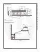
t
PHL
Propagation Delay Time
HIGH-to-LOW
C = 120pF, t
P
= 1µs,
R
E
=
(2)
, Figure 1
All 100 330 ns
t
r
Rise Time C = 120pF, t
P
= 1µs,
R
E
=
(2)
, Figure 1
All 7.5 ns
t
PLH
Propagation Delay Time
LOW-to-HIGH
C = 120pF, t
P
= 1µs,
R
E
=
(2)
, Figure 1
All 150 330 ns
t
f
Fall Time C = 120pF, t
P
= 1µs,
R
E
=
(2)
, Figure 1
All 12 ns
Data Rate All 5 MHz
Symbol Parameters Test Conditions Min. Typ.* Max. Units
V
ISO
Input-Output Isolation Voltage f = 60 Hz, t =1 sec. 7500 V
PEAK
C
ISO
Isolation Capacitance V
I-O
= 0V, f = 1 MHz 0.4 0.6 pF
R
ISO
Isolation Resistance V
I-O
= ±500 VDC 10
11
Ω