OSPREY CAMERA SERIES CAM/CCD-2KCL.TDI CAM/CCD-4KCL.TDI ULTRA-HIGH PERFORMANCE With CameraLinkTM Fairchild Imaging • CAM/CCD 2KCL.TDI & CAM/CCD-4KCL.
EMC Conformance This equipment has been tested and found to comply with the limits for a Class A digital device, pursuant to Part 15 of the FCC Rules. This product fulfills the following requirements of the standards and carries the CE marking. EMC: FCC Part 15, Subpart B EN 6100-6-4:2001 EN 6100-6-2:2001 EN6100-3-2:2000 EN 6100-3-3:1995/A1:2001 Fairchild Imaging • CAM/CCD 2KCL.TDI & CAM/CCD-4KCL.
FAIRCHILD IMAGING OSPREY CAMERA SERIES USER’S MANUAL CAM/CCD-2KCL.TDI & CAM/CCD-4KCL.TDI Revision B December 14, 2004 © 2004 Fairchild Imaging, Inc.. PRELIMINARY DOCUMENT The information in this manual is preliminary. All information provided in this manual is believed to be correct at the time of writing. No responsibility is assumed by Fairchild Imaging for its use.
Table of Contents SECTION I Introduction to the CAM/CCD-2KCL.TDI & CAM/CCD-4KCL-TDI High Performance TDI Line Scan Camera..................................................................... 6 1.1 Camera Highlights...................................................................................................... 6 1.2 Camera Specification ................................................................................................. 8 1.3 Image Sensor ...................................................
SECTION 6 Troubleshooting .............................................................................................................. 27 6.1 Check Simple Things First ......................................................................................... 27 6.2 General Solutions....................................................................................................... 27 SECTION 7 Product Support ...............................................................................................
SECTION 1 Introduction to the CAM/CCD-2KCL.TDI & CAM/CCD-4KCL.TDI High Performance TDI Line Scan Camera 1.1 Camera Highlights Description The Osprey TDI camera series is an ultra-sensitive camera design for use in line scan applications that demand high performance under low light conditions. This series of cameras is based upon Fairchild’s CCD525 array, which is used in the very successful U.S. Postal Service Wide Field of View (WFOV) Camera.
Programmability • • Simple menu-based configuration for selection of gain, calibration, test patterns operational control, and diagnostics CameraLinkTM camera-PC communications Usability • • • • Programmable gain, offsets, and controls Internal flat field correction Easy integration “plug compatabile” CameraLinkTM hookup Exposure control Full Spectrum of Applications • • • • • Precision manufacturing inspection Web inspection Sorting and routing Biomedical readout systems Diagnostic systems Fairchild
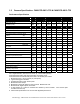
1.2 Camera Specification: CAM/CCD-2KCL.TDI & CAM/CCD-4KCL.TDI Performance Specification 2048 Calibration Conditions Units Min. Data Rate (Strobe) MHz Line Rate (LVAL) KHz 0.3 Units Min Functions 4096 Typ. Max. 25 25 Min 46.0 0.3 Typ Max Min Typ. Max.
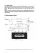
1.3 Image Sensor The family of Osprey cameras use the following Fairchild sensors. The 2K x 96 TDI camera uses the CCD525 sensor and the 4K x 96 TDI camera uses the CCD545 sensor. Both sensors have 13µm square pixels on a 13µm pitch with 100% fill factor. Both the CCD525 and CCD545 sensors have been designed with improved blue response. Both sensors are much more sensitive than single line CCDs used in line scan cameras. 1.4 Block Diagram CCD525 2048 x 96 stages Fairchild Imaging • CAM/CCD 2KCL.
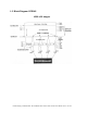
1.5 Block Diagram CCD545 4096 x 96 stages Fairchild Imaging • CAM/CCD 2KCL.TDI & CAM/CCD-4KCL.
1.6 2K/4K TDI Camera Timing Diagram TM TM 4K TDI CameraLink Strobe Period :40 nS Strobe Period :40 nS LVAL Set –Up Time :20 nS LVAL Set –Up Time :20 nS Line Period :20.48 µS Line Period :40.96 µS Blanking :1.8 µS Blanking :1.8 µS ExSync min Set – Up :650 nS ExSync min Set – Up :650 nS 2K TDI CameraLink ExSync min pulse Width :1.8 µS ExSync min pulse Width :1.8 µS Fairchild Imaging • CAM/CCD 2KCL.TDI & CAM/CCD-4KCL.
1.7 Thermal Considerations The Osprey camera series has been carefully designed to separate the camera electronics from the image sensor. Fairchild Imaging advises that if you are going to do any gain or offset corrections that you perform these functions after the camera has been turned on for at least 15 minutes. To do offset correction, cover the lens with your lens cap and to perform a gain calibration, make sure that you have a good light source.
SECTION 2 Camera Hardware Interface 2.1 Installation Overview Before you integrate your camera into your system you should first determine some basic operating parameters such as what resolution you need. Do you know the speed of the object that your camera will be inspecting? One additional point you want to keep in mind is your lighting requirement.
2.2 Connectors, Pinouts, and Cables Figure 2.2-1 TM MDR-26 CameraLink Connector 3M p/n 334 – 34 series Table 2.2-1 Camera Pin # 1 14 2 15 3 16 4 17 5 18 6 19 7 20 8 21 9 22 10 23 11 24 12 25 13 26 Frame Grabber Pin # 1 14 25 12 24.0 11 23 10 22 9 21 8 20 7 19 6 18 5 17 4 16 3 15 2 13 26 Channel Link Signal Inner shield Inner shield X0 X0+ X1X1+ X2X2+ Xclk Xclk+ X3 X3+ SerTC+ SerTCSerTFGSerTFG+ CC1CC1+ CC2CC2+ CC3CC3+ CC4CC4+ Inner shield Inner shield Fairchild Imaging • CAM/CCD 2KCL.TDI & CAM/CCD-4KCL.
Notes: • • • Exterior overshield is connected to the shells of the connectors on both ends. 3M part 14X26-SZLB-XXX-0LC is a complete cable assembly, including connectors. Unused pairs should be terminated in 100 ohms at both ends of the cable. 2.3 Power Supply The camera uses a single voltage input, normally set to 12 Volts @ 0.45 Amps typ. Ripple and noise is required to be < 20 mV RMS. Power is supplied through a Hirose connector. When installing the mating connector, be sure to line up the slots.
SECTION 3 Camera Control 3.1 Quick Start with the CameraLinkTM Interface Follow your Frame Grabber manufacturer’s instructions when inserting the frame grabber card into your PC. Be sure that you install the correct configuration software that matches the camera you are using. At this point your camera should already be connected to the DC power supply and connected to the frame grabber in your PC. To communicate with your camera we have created specific commands.
RSH This command allows you to perform a hard camera reboot. The camera returns … Reboot Started RSS This command allows you to perform a logic reset. No return………..no message INQ This command will show you what camera is connected to your PC. The camera returns … Fairchild Imaging 2K TDI Camera Link Fairchild Imaging 4K TDI Camera Link VER This command will show you the current software version in your camera. The camera returns … FPGA REV.2.5 Micro rev. 0.90 Prod rev. A 1.
TSB This command reads the internal camera temperature. The camera returns … Temp 39.42°C (example) SSM This command allows you to set the Sync mode. When selecting the option you need, first type SSM and press enter and then enter the appropriate single digit number, and then press enter. Value 1 2 3 4 Function Free Run Frame Mode Line Sync External Line Sync, Frame Mode SCM This command allows you to select a correction mode.
CBR This command allows you to change the Baud Rate. You will not see anything on your monitor. Here is a table of stored rates in the camera…Value Function 1 2 3 4 5 9600 19200 38400 (Default) 57600 115200 If you can’t resist changing the baud rate, select the appropriate single digit number and hit enter. LED This command allows you to change the color. When selecting the option you need to, enter the appropriate single digit number and hit enter. Your screen will be blank during this command.
SON Adjust video offset channel 0-3 value 0 – 255 Adjust video offset all channel value value 0 – 255 SOA SGN Adjust video gain channel 0-3 value 0 – 1023 Adjust video gain all channel value 0 – 1023 SGA TDI Set number of TDI stages 2K 4K 1 24 1 4 2 32 2 16 3 48 3 32 4 64 4 64 5 96 5 96 3.
Command Definition Summary SBS Set Bit shift This function allows user to shift 12, 10, 8 bit video SAP Stores all parameters This function allows you to save default or user settings RAP Recalls all parameters This function allows user to recall the factory calibration GSN Get serial number This function allows user to retrieve camera info, e.g.
SECTION 4 Mechanical and Optical Considerations 2K 4K Fairchild Imaging • CAM/CCD 2KCL.TDI & CAM/CCD-4KCL.
4.1 Camera Dimensions and Mounting Facilities The 2K and 4K TDI camera housing is manufactured with high precision. Planar, parallel, and angular sides guarantee precise mounting with high repeatability. The 2K and 4K TDI camera housing is equipped with four M4 mounting holes on the front and two M4 mounting holes on one side and on the bottom of the camera. Use caution in the following ways to avoid stripping threads or stressing the case: • Use only M4 screws.
4.3 Mechanical Drawing of Available Camera Face Mounting “L” Bracket Contact your Fairchild Imaging representative for more details. Fairchild Imaging • CAM/CCD 2KCL.TDI & CAM/CCD-4KCL.
4.4 Lenses Fairchild Imaging does not supply lenses; contact your local optics supplier for available lens models. 4.5 Illumination The amount and wavelengths of light required to capture useful images depend on the particular application. Factors include the nature, speed, and spectral characteristics of objects being imaged, exposure times, light source characteristics, environmental and acquisition system specifics. It is often more important to consider exposure than illumination.
SECTION 5 Handling Instructions 5.1 Electrostatic Discharge The Fairchild Imaging Osprey camera uses TDI technology in a CCD base, and as all such devices, has some limited inherent susceptibility to electrostatic discharge (ESD). All reasonable and customary design steps have been taken to provide ESD protection circuitry.
SECTION 6 Troubleshooting 6.1 Check Simple Things First Remember that the camera is part of the entire acquisition system. You may have to trouble shoot any or all of the following: • Power supply • Frame grabber hardware & software • Light sources • Operating environment • Cabling • Host computer • Optics • Encoder 6.2 General Solutions Connections The first step in trouble shooting is to verify that your camera has all the correct connections.
EXSync Exsync must toggle (200 Hz min.). The camera will not output lines if ExSync is restricted to logic HIGH or logic LOW. Using an oscilloscope, check the camera end of the control signal cable to verify that ExSync toggles. Offset Variation or Drifts The camera will experience offset drift and the dark level will increase if the camera’s EXSYNC signal stops or is below 200 Hz. The camera is meant to be run with a continuous EXSYNC frequency.
Check the exposure time. If the images are too dark try increasing the exposure. Try decreasing the exposure if they are too bright. Check your light source. If the images are too dark, try increasing your light intensity. Try decreasing the intensity if they are too bright. Check your gain setting. If the images are too dark, try increasing the gain. Try decreasing the gain if they are too bright. Images look noisy Make sure that you are using a DC light source.
SECTION 7 Product Support If after troubleshooting your camera, and you still have problems, collect the following data about your application and situation and call Fairchild Imaging Customer Support. Note: You may also want to photocopy this page to fax to Fairchild Imaging @ 408735-7352 Customer name Organization name Customer phone number Customer Fax number Complete Product Model Number (e.g.