www.fairchildsemi.com FEB157-001 User’s Guide Offline High Brightness LED Driver Evaluation Board Featured Fairchild Product: FAN7554 © 2007 Fairchild Semiconductor Page 1 of 17 Rev 1.
www.fairchildsemi.com Contents 1. Introduction ............................................................................................................................................3 1.1 Product Description ..........................................................................................................................3 1.2 Circuit Description ...........................................................................................................................3 2.
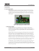
www.fairchildsemi.com 1. Introduction 1.1 Product Description A high brightness LED evaluation board has been developed using the Fairchild Semiconductor FAN7554D PWM controller. The board has the capability of driving one, two or three Lumiled, or similar LEDs. The output current is user selectable at 350mA, 700mA, or 1A. The current is selectable by inserting or removing jumpers JP1 and JP2 on the evaluation board. The board is designed to operate over the universal AC line range of 90Vac to 270Vac.
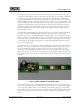
www.fairchildsemi.com Since the output current is being controlled instead of the output voltage, the output voltage will actually vary with the number of LEDs on the output. The same applies to the auxiliary winding that provides the bias supply to the FAN7554D. Consequently, the transformer had to be designed to provide enough bias when powering one LED. Then when powering three LEDs, the bias voltage is significantly higher.
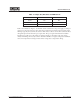
www.fairchildsemi.com Table 1: Jumper JP1/JP2 Status and LED Current LED Current JP1 Status JP2 Status 350mA Out Out 700mA In Out 1A In In Refer to the schematic in Figure 3. As the LED current returns back to the power supply, it develops a voltage across the sense resistor(s). Once this voltage reaches the base-emitter junction voltage of the NPN Q2, typically about 650mV, the transistor will conduct collector current.
www.fairchildsemi.com 2. Electrical Requirements 2.1 Input Requirements Voltage range: 90Vrms to 270Vrms Frequency: 47Hz to 63Hz 2.2 Output Requirements The FEB157 board will power one, two, or three high brightness LEDs (Lumiled or similar) at user selectable load currents of 350mA, 700mA, or 1A. © 2007 Fairchild Semiconductor Page 6 of 17 Rev 1.
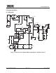
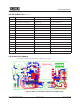
www.fairchildsemi.com 3. Designed Solution 3.1 Schematic LF1 2 R1 5.6Ω 1W 3 R2 22kΩ 2010 C2 47µF 450V BD1 DF10S C3 1000pF 1kV R3 22kΩ 2010 C1 0.1µF T1 EFD20 Core/Bobbin 1 Lm = 610µH 2 D1 RS1M R4 10Ω 1206 F1 1A, 250V R5 150kΩ 2010 3 R6 150kΩ 2010 Q1 FQD2N80 R7 22Ω 0805 C15 100pF D2 Prov. for MMBD4148 TP3 Vref C6 0.01µF IC2 FOD817A R10 10kΩ 1% 0603 7 6 5 R20 1kΩ 2010 C12 47µF 50V R14 1.8Ω, 2010 JP1 R18 100Ω 0603 FB S/S 2 IS 3 C8 1µF J2 JP2 C4 47µF 50V R16 1.
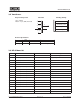
www.fairchildsemi.com 3.2 Transformer Required Components Schematic Core = EFD20 Bobbin = 10 pin; SMD; Horizontal Winding Stackup 1 Vcc 25 T 1/2 Pri - 36 T 2 3 1/2 Primary - 36 T 8 1/2 Pri - 36 T Secondary - 10T Output - 10 T 4 1/2 Primary - 36 T 6 Vcc - 25 T 5 Electrical Specifications Pin Inductance 1-3 Leakage 1-3 Spec. 537.0 - 656.0 uH Remarks 100 kHz, 0.10 Vrms All other windings shorted 3.3 Bill of Materials Sch Ref Vendor Part Number Description BD1 Fairchild DF10S 1.
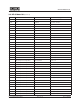
www.fairchildsemi.com 3.3 Bill of Materials (Continued) Sch Ref Vendor Part Number Description Conn1 Phoenix Contact 1729018 2 position terminal block Conn2 Tyco 535676-5 6 position connector D1 Fairchild RS1M 1A, 1000V, SMA D2 Fairchild Prov. for MMBD4148 D3 Fairchild BAS21 0.
www.fairchildsemi.com 3.3 Bill of Materials (Continued) Sch Ref Vendor Part Number Description R17 NIC Components or Equivalent NRC06J511TR 510Ω, 1/10 W, 0603 R18 NIC Components or Equivalent NRC06J101TR 100Ω, 1/10 W, 0603 R19 Prov.
www.fairchildsemi.com Figure 5: Silkscreen/Component Placement of Top Side Layer Figure 6: Silkscreen/Component Placement of Bottom Side Layer © 2007 Fairchild Semiconductor Page 11 of 17 Rev 1.
www.fairchildsemi.com 4. Test Results 4.1 Regulation 4.1.1 Line Regulation This graph illustrates the regulation of the output current over line voltage for the three possible settings, 350mA, 700mA, and 1A. 1200 LED Current (mA) 1000 800 1 LED 2 LEDs 3 LEDs 600 400 200 0 90 120 270 Input Voltage (Vac) Figure 7: LED Current vs. Line Voltage © 2007 Fairchild Semiconductor Page 12 of 17 Rev 1.
www.fairchildsemi.com 4.2 Efficiency The efficiency data shown is for the converter with a load of one, two and three LEDs driven at 1A. 90 80 Efficiency (%) 70 60 1 LED @ 1 A 50 2 LEDs @ 1 A 40 3 LEDs @ 1 A 30 20 10 0 90 120 270 Input Voltage (V) Figure 8: Converter Efficiency Data Plotted Against Increasing Line Input for LED Current of 1A. © 2007 Fairchild Semiconductor Page 13 of 17 Rev 1.
www.fairchildsemi.com 4.3 Steady State Operation Figure 9: Steady State Waveforms at 90Vac with Three LEDs at 1A Figure 10: Steady State Waveforms at 270Vac with One LED at 350mA © 2007 Fairchild Semiconductor Page 14 of 17 Rev 1.
www.fairchildsemi.com 4.4 Start up The startup profile is captured at 90Vac and 270Vac with a load of three LEDs operating at a current of 1A. Figure 11: Startup Profile at 90 Vac with Three LEDs at 1A Figure 12: Startup Profile at 270Vac with Three LEDs at 1A © 2007 Fairchild Semiconductor Page 15 of 17 Rev 1.
www.fairchildsemi.com Warning and Disclaimer: This Evaluation Board may employ high voltages so appropriate safety precautions should be used when operating this board. Replace components on the Evaluation Board only with those parts shown on the parts list in the User's Guide. Contact an authorized Fairchild representative with any questions.
www.fairchildsemi.