UmSITETM5 Quick Start Manual Contents: 1. UmSITETM5 1.1 Mechanical specification 1.2 Software specification 1.3 Hardware Options 2. Installation 2.1 Antennas installation 2.2 Getting started 2.3 Test call 2.4 Log in 2.5 IP and network configuration (optional) 2.6 Base station sensors 1. UmSITETM5 The UmSITETM5 is an IPbackhaul GSM Base Station, seamlessly integrating functionality that is usually provided by GSM components such as BSC, MSC, VLR, HLR and SMSC.
maintenance and upgrade, and covering everything from transmit power control to end user features. 1.1 Mechanical specification Enclosure ● ● Dimensions: 300 mm x 176 mm x 190 mm (210 mm with mounting brackets) Weight: 8.
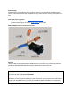
Power supply Fairwaves does not provide the power supply by reason of various places use different power sources. Fairwaves products are compatible with any power sources, including solar panels, as well. List of the power supplies: ● ● Outdoor IP65 power supply: Mean Well HLG60H15A Indoor power supply: Any basic laptop charger can be used Power/COMport wires connection schema Antenna UmSITETM5 can be supplied without GSM antennas.
the Census; or, (2) Extend coverage on a secondary basis into cellular unserved areas, as those areas are defined in Title 47, CFR §22.949 (Code of Federal Regulations), the antenna gain must not exceed 23 dBi. 1.
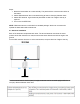
Steps: 1. Mount the base station to a mast vertically. The panel with the connectors should be at the bottom. 2. Attach GSM antennas. We recommend having at least 10 feet (3m) between them. 3. Attach GPS antenna. A good antenna placed with a clear line of sight to the sky is required. 4. Turn on the UmSITETM5. NOTE: GSM antennas are not included in a standard package. We do not recommend to operate the base station without antennas. 2.1 Antennas installation Each of the antennas complement each other.
NOTE: Every cell is configured with a BCCH carrier. Generally, the TRX ID of BCCH is fixed to be the smallest TRX ID in the cell. Therefore, TRX1 antenna has to be situated below the TRX2 antenna. For example, if the connection would be established when the TRX1 antenna is higher and then it has been assigned to a timeslot of the lower antenna TRX2, call connection could be lost. The antenna attached to the TRX1 should not have an advantage by height in that particular case. 2.2 Getting started 1.
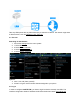
Take any GSM phone with any SIM card and try to search the network. The network might have a different name, such as Fairwaves, 1011, Test, etc. 2.3 Test call Searching for the Network 1. 2. 3. 4. 5. Launch the Settings from the menu system. 1. Select More 2. Select Mobile networks 3. Select Network operators 4. Select Search networks Options: ● 1002 echo call (listen yourself) ● *#100# to figure out the number that was assigned to your phone. 2.
Connect laptop to the UmSITETM5 via Ethernet cable. NOTE: Make sure your interface in the same subnet as the UmSITETM5 and has IP like 192.168.50.101 1. Run PuTTY 2. Type IP address: 192.168.50.100 Login: fairwaves Password: fairwaves You may use a defferent client software for remote access, but we recommend PuTTY (you can download it at www.putty.org ). PuTTY is an open source SSH and telnet client, for the Windows platform.
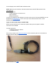
You can find a number of the COM port at the Desktop manager. For the Linux user minicom shell> minicom D/dev/ttyUSB0 b38400 o 2.5 IP and network configuration eth0 192.168.10.10 This is internal interface linked to the UmTRX. Do not edit this eth1 Configured to obtain IP address through DHCP. In case of recovery, it also has a static IP 192.168.50.100 Edit eth1 in /etc/network/interfaces.d/ In order to change network configuration Shell> sudo nano /etc/network/interfaces.
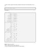
In order to obtain insights of temperature, voltage and TRX power of the base station you can run: Shell> umtrx_query_sensors The output is: Shell> Sensors: TempA = 34.312500 C TempB = 35.187500 C VoltagePR1 = 2.580000 V VoltagePF1 = 3.280000 V VoltagePR2 = 0.760000 V VoltagePF2 = 0.000000 V Voltagezero = 0.000000 V VoltageVin = 23.620000 V VoltageVinPA = 23.640000 V VoltageDCOUT = 21.640000 V TRX 1 power detector: VPF = 3.26 V PF = 65.2 dBm VPR = 2.58 V PR = 51.6 dBm VSWR = 1.53 Gamma = 0.
> 10dB = partly good (probably bad antenna or water in cable/connector) > 12dB = good > 15dB = excellent