
Installation Guide
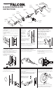

8. INSTALL INSIDE TRIM
A. Place mounting plate over chassis.
B. Insert screws and tighten.
C. Locate the notch on the edge of rose towards
the bottom and push in until flush with face of
door.
D. Align lever with spindle and push until button
engages with hole.
E. Check function before closing door.
9. REMOVING LEVERS
A. For outside levers only: Turn key or button
45° clockwise and hold.
B. Depress lever catch and pull off lever and
cylinder.
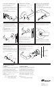
10. INSTALLING STANDARD
CYLINDERS INTO LEVERS
A. Insert cylinder into lever.
B. Insert key into cylinder to hold and align cylinder.
C. Insert cylinder retainer into lever to secure cylinder.
11. INSTALLING STANDARD
CYLINDERS & LEVERS
A. Align hole in lever with lever catch on
spindle assembly and slide lever up to lever
catch.
B. For outside levers only: Turn key or button
45° clockwise and hold.
C. Push lever in to engage lever catch.
D. Check function before closing door.
12. REMOVING IC CORE
A. Unlock lockset.
B. Turn control key 15° clockwise or until key stops.
C. Pull key to remove IC core.
LEVER
CATCH
45°
13. INSTALLING IC CORE
A. With control key in core rotate key 15°
clockwise and insert fully into lever.
B. Turn the key counter-clockwise and
remove key.
C. Check function before closing door.
14. REMOVING IC LEVERS
A. With IC core removed, using a screwdriver,
depress lever catch and pull lever to remove.
LEVER CATCH
15. INSTALLING IC LEVERS
A. Push lever in until lever catch engages with
lever.
CYLINDER
SPRING
PIN
TAILPIECE
CAP
16. TAILPIECE INSTALLATION
A. Insert spring and pin into cylinder.
B. Place tailpiece into cap.
C. Thread cap onto the cylinder.
NOTE: The cap must be properly adjusted. If
too loose, excessive plug end play will prevent
the key from being withdrawn. If too tight, the
plug will drag and be difficult to rotate with the
key.
17. DUMMY INSTALLATION
A. Remove lever and rose (see step 9).
B. Position mounting plate as required with lever
catch towards door edge.
C. Fasten mounting plate to door using four #8
combo screws provided.
D. Install rose and lever (see step 8).
DOOR
EDGE
LEVER
CATCH
18. CYLINDER TIMING
FOR B371:
A. Install lock on door as shown in steps 1 thru 8.
B. Using a 1/4” diameter philips screwdriver, turn
key spindle until stop and lever is locked.
C. Turn back the key spindle 1/2 turn.
D. If IC go to E. Remove standard cylinder lever.
E. Insert cylinder into lever as shown in step 10.
F. Insert lever and cylinder onto spindle as shown
in step 11.
G. Repeat A. thru F. for opposite side.
H. Check operation:
Outside - turn key CCW 270° to unlock.
turn key CW 180° to lock.
Inside - turn key CW 270° to unlock.
turn key CCW 180° to lock.
FOR B391 & B561:
A. Install lock on door as shown in steps 1 thru 8.
B. Using a 1/4” diameter philips screwdriver, turn
key spindle until stop and lever is unlocked.
C. If IC go to G. Remove standard cylinder lever.
D. Insert cylinder into lever as shown in step 10.
E. Slide lever and cylinder onto the spindle and
push the cylinder in to engage the key spindle.
F. Insert key into cylinder and turn CW 45° as
shown in step 9. Go to step H.
G. For IC: Insert cylinder into lever as shown in
step 12.
H. Check operation:
Outside - turn key CW 360° to unlock.
turn key CC W 360° to lock.
LEVER
CATCH
HOLE
800-266-4456
©
2008 Schlage Lock Company
Printed in Country
031728-000-70 Rev. 04/08-b