USER GUIDE & INSTALLATION INSTRUCTIONS Classic Deluxe 110 Dual Fuel Australia U111288-02
Contents 1. 2. 1 8. Troubleshooting 26 Personal Safety 1 Electrical Connection Safety 2 9.
1. Before You Start... Your cooker should give you many years of trouble-free cooking if installed and operated correctly. It is important that you read this section before you start. Personal Safety This appliance is for cooking purposes only. It must not be used for other purposes, for example heating a room. Using it for any other purpose could invalidate any warranty or liability claim. Besides invalidating claims this wastes fuel and may overheat the control knobs.
• DO NOT use a steam cleaner on your cooker. • Always keep combustible materials, e.g. curtains, and flammable liquids a safe distance away from the cooker. • Make sure that the gas supply is turned on and that the cooker is wired in and switched on. • DO NOT spray aerosols in the vicinity of the cooker while it is on. • In your own interest and that of safety, it is law that all gas appliances be installed by a qualified person(s).
the grill or ovens are in operation the fan will run to cool the fascia and control knobs. by the manufacturer of the cooking appliance or indicated by the manufacturer of the appliance in the instructions for use as suitable or hob guards incorporated in the appliance. The use of inappropriate guards can cause accidents. Ventilation The use of a cooking appliance results in the production of heat and moisture in the room in which it is installed.
along the back of the cooker) for warming plates, dishes, drying tea towels or softening butter. Fig. 1.1 • DO NOT use water on grease fires and never pick up a flaming pan. Turn the controls off and then smother a flaming pan on a surface unit by covering the pan completely with a well fitting lid or baking tray. If available, use a multi-purpose dry chemical or foam-type fire extinguisher. • DO NOT modify this appliance.
door glass since they can scratch the surface, which may result in shattering of the glass. • underneath it, otherwise the knobs may become hot. Make sure the shelves are pushed firmly to the back of the oven. DO NOT close the door against the oven shelves. • DO NOT use aluminium foil to cover shelves, linings or the oven roof. • When the oven is on, DO NOT leave the oven door open for longer than necessary, otherwise the control knobs may become very hot.
6 • Before you remove any of the grill parts for cleaning, make sure that they are cool or use oven gloves. • DO NOT use any abrasive substances on the grill and grill parts. • DO NOT put the side runners in a dishwasher. • DO NOT put the burner heads in a dishwasher. • NEVER use caustic or abrasive cleaners as these will damage the surface. • DO NOT use steel wool, oven cleaning pads or any other materials that will scratch the surface. • NEVER store flammable materials in the drawer.
2. Cooker Overview Fig. 2.1 A B 1 O 1 2 2 3 3 C E M D F ArtNo.212-0019 - 110 DF Classic Deluxe front view The 110 dual fuel cooker (Fig. 2.1) has the following features: A. Four hotplate burners with a wok burner and ceramic multi-zone hotplate B. Control panel C. Glide-out Grill™ D. A multi-function oven E. Fan oven F. Bread proving / Storage drawer Fig. 2.2 Hotplate Burners The drawing by each of the central knobs indicates which burner that knob controls.
If, when you let go of the control knob, the burner goes out, then the FSD has not been bypassed. Turn the control knob to the ‘OFF’ position and wait for one minute before you try again, this time making sure to hold in the control knob for slightly longer. Fig. 2.3 Adjust the flame height to suit by turning the knob counterclockwise (Fig. 2.3). On this cooker the low position is beyond high, not between high and off.
The Ceramic Hotplate Fig. 2.11 The hotplate area on the left-hand side is dual purpose. It can be used either as a ceramic hob to heat a pan in the usual way (Fig. 2.11) or it can be used to heat the supplied griddle plate. The rear area, marked with a ring is for cooking with a pan. There are two elements that allow either the whole of the area to be heated or just the rear half. To use the rear ring turn the control counter-clockwise (Fig. 2.12).
The Griddle Plate Fig. 2.16 The griddle plate (Fig. 2.16) is designed to fit securely on the locating pins over the ceramic heating area (Fig. 2.17). Do not try to use it over one of the gas burners. It will not be securely held and you may damage the non-stick finish. There are two elements that allow either the whole of the area to be heated or just the rear half. To heat the whole area, turn the knob clockwise (Fig. 2.18). To heat the rear ring only, turn it counter-clockwise (Fig. 2.19). Fig. 2.
Bread Proving Drawer Fig. 2.22 The Bread Proving Drawer is found on the right at the base of the cooker (Fig. 2.22). Within the Bread Proving Drawer there are slots in the base to allow warmed air to flow through into the drawer from the element underneath. The Bread Proving Drawer temperature is ideal for proving all sorts of yeast dough from sweet to savoury, gluten free to sourdough, dough made from fresh yeast and dried, bread mixes and recipes from the Rangemaster Good Housekeeping Cookery book.
The Ovens Fig. 2.24 The clock must be set to the time of day before the ovens will work. See the following section on ‘The Clock’ for instructions on setting the time of day. References to ‘left-hand’ and ‘right-hand’ ovens apply as viewed from the front of the appliance. Multi-function oven The left-hand oven is a programmable multifunction oven (Fig. 2.24) The right-hand oven is a fan oven (Fig. 2.25). ArtNo.321-0006 - Multi-function oven The Fan Oven Fig. 2.
Multifunction Oven Functions Fan Assisted Oven This function operates the fan, circulating air heated by the elements at the top and the base of the oven. The combination of fan and conventional cooking (top and base heat) makes this function ideal for cooking large items that need thorough cooking, such as a large meat roast. Rapid Response The Rapid Response setting enables you to preheat the oven faster than normal.
Operating the Ovens Fig. 2.26 Conventional and Fan Ovens Fan ovens circulate hot air continuously, which means faster, more even cooking. The recommended cooking temperatures for a fan oven are generally lower than a conventional oven. ArtNo.235-0004 Classic DL oven 1 Turn the oven knob to the desired temperature (Fig. 2.26). The oven indicator light will glow until the oven has reached the temperature selected (Fig. 2.27). It will then cycle on and off during cooking.
Accessories Fig. 2.30 Shelf guard Oven Shelves The oven shelves (Fig. 2.30) are retained when pulled forward but can be easily removed and refitted. Pull the shelf forward until the back of the shelf is stopped by the shelf stop bumps in the oven sides (Fig. 2.31). Front Lift up the front of the shelf so the back of the shelf will pass under the shelf stop and then pull the shelf forward (Fig. 2.32). Fig. 2.
5. Using the Glide-out Grill™ DocAUS.020-0004 - Overview - 110DF - Elan Fig. 5.2 Fig. 5.1 Nearest to the element Middle High Middle Low Furthest from the element Four grill height positions refer to Fig. 5.5 Fig. 5.4 Fig. 5.3 ArtNo.235-0007 - Classic DL grill control ArtNo.235-0007 - Classic DL grill control To switch on both elements To switch on the right half element Four grill height positions Nearest to the element Fig. 5.
6. 6 Button clock Automatic dimming Fig. 6.1 Providing there are no automatic programs set, and the minute minder is not active, your clock will automatically dim during the hours between 22:00 and 06:00. Minute Minder ArtNo.302-0002 - 6BC annotated A B C D E Step. 1 Press and hold the [] button F A – Minute minder, B – ‘Cook’ time, C – ‘Stop’ time, D – Manual, E & F – Time setting buttons Symbol Function [] Minute Minder is active hold Notes ArtNo.
Setting a cook duration (main oven only) To start and stop the ovens automatically (main oven only) You have set the required temperature and function mode and you would like the oven to automatically stop. Step. 1 You have set the required temperature and function mode and you would like the oven to automatically stop. Press either [+] or [-] buttons. Step. 1 Press either [+] or [-] buttons to set cooking duration. ArtNo.302-0002 - 6BC annotated ArtNo.302-0002 - 6BC annotated hold hold Step.
4. Cooking Tips Tips on cooking with the timer General oven tips If you want to cook more than one dish, choose dishes that require approximately the same cooking time. However, dishes can be ‘slowed down’ slightly by using small containers and covering them with aluminium foil, or ‘speeded up’ slightly by cooking smaller quantities or placing them in larger containers. The wire shelves should always be pushed firmly to the back of the oven.
5. Cooking Table The oven control settings and cooking times given in the table below are intended to be used as a guide only. Individual tastes may require the temperature to be altered to provide a preferred result. Food is cooked at lower temperature in a fan oven than in a conventional oven. When using recipes, reduce the fan oven temperature by 10 °C and the cooking time by 5-10 minutes. The temperature in the fan oven does not vary with height in the oven so you can use any shelf.
7. Cleaning Your Cooker Fig. 7.1 Essential Information A Isolate the electricity supply before carrying out any thorough cleaning. Allow the cooker to cool. C B E D n Never use paint solvents, washing soda, caustic cleaners, biological powders, bleach, chlorine based bleach cleaners, coarse abrasives or salt. n Do not mix different cleaning products – they may react together with hazardous results.
Ceramic Hotplate Fig. 7.5 Daily Care First of all, make sure that the heat indicator light is off and that the cooking surface is cool. Apply a small dab of ceramic cleaning cream in the centre of the area to be cleaned. Dampen a clean paper towel and work the cream onto the cooking surface. As a final step, wipe the cooking surface with a clean, dry paper towel.
Grills Fig. 7.6 The grill pan and trivet should be washed in hot soapy water. Alternatively, the grill pan can be washed in a dishwasher. After grilling meats or any foods that soil, leave to soak for a few minutes immediately after use. Stubborn particles may be removed from the trivet using a nylon brush. Fig. 7.7 n Before you remove any of the grill parts for cleaning, make sure that they are cool, or use oven gloves. n DO NOT use any abrasive substances.
Control Panel and Doors Fig. 7.10 Avoid using any abrasive cleaners, including cream cleaners. For best results, use a liquid detergent. The same cleaner can also be used on the doors. Alternatively, use a soft cloth wrung out in clean hot soapy water. You can use the same method for cleaning the control panel and knobs. After cleaning, polish with a dry cloth. Glass Fronted Door Panels ArtNo.
Cleaning Table Cleaners listed (Table 7.1) are available from supermarkets or electrical retailers as stated. For enamelled surfaces use a cleaner that is approved for use on vitreous enamel. Regular cleaning is recommended. For easier cleaning, wipe up any spillages immediately. Hotplate Part Finish Recommended Cleaning Method Hob top (including burner heads and caps) Enamel, stainless steel, aluminium Hot soapy water, soft cloth. Any stubborn stains remove gently with a nylon scourer.
7. Troubleshooting Hotplate/Cooktop ignition or hotplate burners faulty Food is cooking too slowly, too quickly, or burning Is the power on? Is the clock illuminated? Cooking times may differ from your previous oven. If not, there maybe something wrong with the power supply. Check that you are using the recommended temperatures and shelf positions – see the oven cooking guide. The oven control settings and cooking times are intended to be used only as a guide.
Oven light is not working Fig. 7.1 The bulb has probably burnt out. You can buy a replacement bulb (which is not covered under the warranty) from a good electrical shop. Ask for a 40 W - 230 V halogen lamp (G9) (Fig. 7.1). Turn off the power at the circuit breaker. Before removing the existing bulb, turn off the power supply and make sure that the oven and bulb have cooled. Open the oven door and remove the oven shelves. Fig. 7.2 Remove the bulb cover by turning it a quarter turn, counterclockwise.
INSTALLATION Check the appliance is electrically safe when you have finished. 7. Service and Spares Firstly, please complete the appliance details below and keep them safe for future reference – this information will enable us to accurately identify the particular appliance and help us to help you. Filling this in now will save time and inconvenience if you later have a problem with the appliance. It may also be of benefit to keep your purchase receipt with this leaflet.
INSTALLATION Check the appliance is electrically safe and gas sound when you have finished. 10. Installation Safety Requirements and Regulations n Provision of Ventilation This appliance is not connected to a combustion products evacuation device. Particular attention shall be given to the relevant requirements regarding ventilation. Please read the Before you start... chapter, before you begin any installation and maintenance work on this appliance.
INSTALLATION Check the appliance is electrically safe and gas sound when you have finished. You will need the following equipment to complete the cooker installation satisfactorily: Flat shelves Handyrack • Flexible gas hose. • Gas pressure tester/manometer. ArtNo.324-0003 Handyrack • Multimeter: For electrical checks. You will also need the following tools: 1. Electric drill Roasting tin 2. Masonry drill bit (only required if fitting the cooker on a stone or concrete floor) 3.
INSTALLATION Check the appliance is electrically safe and gas sound when you have finished. Positioning the Cooker Fig. 10.1 The diagram (Fig. 10.1) shows the minimum recommended distance from the cooker to nearby surfaces as given in AS/NZS 5601. E Hob D * Where the appliance is installed next to cabinetry, the cabinet material must be capable of withstanding 70°C. If this appliance is installed near vinyl wrapped surfaces, use an installation kit available from the vinyl-wrap supplier.
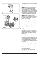
INSTALLATION Check the appliance is electrically safe and gas sound when you have finished. Moving the Cooker n On no account try and move the cooker while it is plugged into the electricity supply. n The cooker is very heavy, so take great care. Fig. 10.3 We recommend that two people manoeuvre the cooker. Make sure that the floor covering is firmly fixed, or removed, to prevent it being disturbed when moving the cooker around.
INSTALLATION Check the appliance is electrically safe and gas sound when you have finished. Fitting the Stability Bracket and Chain Fig. 10.6 n Unless properly installed, the cooker could be tipped by leaning on the door. Injury might result from spilled hot liquids or from the cooker itself. Alternative positions for stability location bracket IMPORTANT: The cooker must be set to the correct height and levelled before the stability bracket is installed. Fig. 10.
INSTALLATION Check the appliance is electrically safe and gas sound when you have finished. With a stability chain fitted, release it as you ease the cooker out. Do not forget to refit it when you replace the cooker. Fig. 10.10 Pipework When you replace the cooker, again check behind to make sure that the electricity cable and gas hose are not caught or trapped. Pipework Gas Connection Must be in accordance with the relevant standards.
INSTALLATION Check the appliance is electrically safe and gas sound when you have finished. Electrical Connection Fig. 10.12 This appliance must be installed by a qualified electrician to comply with with current AS/NZS 3000 Wiring Rules and regulations in force. Make sure that the mains characteristics (voltage, nominal, power, etc.) match the ratings indicated on the cooker data plate. ArtNo.
INSTALLATION Check the appliance is electrically safe and gas sound when you have finished. Connection in New Zealand Fig. 10.14 Type of cord in accordance with IEC 60227 with a minimum rating of 90°C. Cord size recommended for this application is 3 x 10 mm², three-core cable (Power cables may be sized to take into account the coincidence factor AS/NZS 60335.2.6:2014). Rating of the plug is 32 Amp, in accordance with AS/NZS 3112.
INSTALLATION Check the appliance is electrically safe and gas sound when you have finished. Final Checks Fig. 10.19 Note: The clock must be set before the ovens will work. See ‘The Clock’ section for instructions on setting the time of day. Hotplate Check ArtNo.215-0026 - Handle gaskets fixed Check each burner in turn (refer to the “Hotplate Burners” on page 7 of the instructions). Grill Check Fig. 10.20 Turn on the grill control and check that the grill heats up.
WARNING – SERVICING TO BE CARRIED OUT ONLY BY AN AUTHORISED PERSON Disconnect from electricity and gas before servicing. Check appliance is safe when you have finished. 11. Conversion to LP Gas Conversion from Natural Gas (1.0 kPa) to LPG X Propane (2.54 kPa) Fig. 11.1 A B ArtNo.311-0010 Injectors n A suitably competent person must perform the conversion. After conversion the installation must comply with the relevant regulations and also the local electricity supply company requirements.
WARNING – SERVICING TO BE CARRIED OUT ONLY BY AN AUTHORISED PERSON Disconnect from electricity and gas before servicing. Check appliance is safe when you have finished. Set the Governor Fig. 11.4 Unscrew the governor’s brass top. In the base of the brass top is a plastic snap-in converter device (Fig. 11.4). To convert the governor, snap the device out of the top and refit it the other way round. The snap-in converter device is marked to show the gas for which it is set (Fig. 11.5). ArtNo.
WARNING – SERVICING TO BE CARRIED OUT ONLY BY AN AUTHORISED PERSON Disconnect from electricity and gas supplies before servicing. Check appliance is safe when you have finished. 12. Servicing Fig. 12.1 ArtNo.210-0009 - Classic removing the handles Fig. 12.2 n BEFORE SERVICING ANY GAS CARRYING COMPONENTS TURN OFF THE GAS SUPPLY n Check the appliance is gas sound after completion of service. When checking for gas leaks do not use washing up liquid – this can corrode.
WARNING – SERVICING TO BE CARRIED OUT ONLY BY AN AUTHORISED PERSON Disconnect from electricity and gas supplies before servicing. Check appliance is safe when you have finished. 2 Hotplate Fig. 12.3 2.1 To Remove the Hotplate Top DISCONNECT FROM THE ELECTRICITY SUPPLY. Caution - The ceramic hob material is much more sensitive to scratches on the underside than the top. Take care not to touch or scratch the underside of the ceramic as this will weaken the material and cause the top to shatter.
WARNING – SERVICING TO BE CARRIED OUT ONLY BY AN AUTHORISED PERSON Disconnect from electricity and gas supplies before servicing. Check appliance is safe when you have finished. 2.5 To Change a Hotplate Burner Thermocouple 3.3 To Remove the Electronic Timer DISCONNECT FROM THE ELECTRICITY SUPPLY. DISCONNECT FROM THE ELECTRICITY SUPPLY. Remove the control panel and hotplate (see 1.2 & 2.1). Pull off the timer control button(s) and remove the control panel (see 1.2).
WARNING – SERVICING TO BE CARRIED OUT ONLY BY AN AUTHORISED PERSON Disconnect from electricity and gas supplies before servicing. Check appliance is safe when you have finished. 5 Ovens Fig. 12.5 5.1 To Replace an Oven Thermostat DISCONNECT FROM THE ELECTRICITY SUPPLY. Remove the handrail (see 1.1), control panel (see 1.2) and hotplate top (see 2.1). Open the oven doors and remove the oven furniture.
WARNING – SERVICING TO BE CARRIED OUT ONLY BY AN AUTHORISED PERSON Disconnect from electricity and gas supplies before servicing. Check appliance is safe when you have finished. 5.2 To Remove an Oven Element Thermal Cut-out Fig. 12.7 DISCONNECT FROM THE ELECTRICITY SUPPLY. Pull the cooker forward to gain access to the cover box. Undo the cover screws and lift clear. The cut-out is located on the earth plate beside the oven element connections. Disconnect the cut-out wiring.
WARNING – SERVICING TO BE CARRIED OUT ONLY BY AN AUTHORISED PERSON Disconnect from electricity and gas supplies before servicing. Check appliance is safe when you have finished. 5.6 To Remove the Left-hand Oven Bottom and Top Elements Fig. 12.8 DISCONNECT FROM THE ELECTRICITY SUPPLY. ArtNo.322-0002 Oven bottom element access Bottom Element B Pull the cooker forward to access the cover boxes at the rear of the unit. Remove the fixings that secure the cover and lift it clear.
WARNING – SERVICING TO BE CARRIED OUT ONLY BY AN AUTHORISED PERSON Disconnect from electricity and gas supplies before servicing. Check appliance is safe when you have finished. 6.4 To Replace the Main Oven Door Outer Panel Fig. 12.13 Move the cooker forwards to gain access to the sides. Open the oven door slightly and remove the 4 front panel fixing screws from the door sides (2 each side), (Fig. 12.13). Carefully lift off the outer door panel.
11. Circuit Diagram r r X07 r X26 bk b br bk X02 bk X26 v r b br X03 X27 X04 v b r 2 P2 1 P1 v br y v br P1 r X33 b w v P2 b b X08 X10 X27 b r o r gr X11 w b X09 b gr 8 y o X16 6 v P7 r w P6 5 P5 7 w y o o bk X06 4 X26 P3 P2 P1 br br bk 1.1kW b P4 3 1 v P8 2 r r X32 br v br v br v br br v v b X26y br y X26 r d e c b a v P038434 1 2 y y Y f bk y X12 X24 X34 X34 br bk X28 1.
14. Technical Data This cooker is designed for use on Natural gas, although a conversion for LP (LPG X Propane (2.54 kPa)) gas is included. INSTALLER: Please leave these instructions with the user. DATA BADGE LOCATION: Cooker back. The serial number is repeated on the badge below the left-hand oven door opening. Country of Destination: Australia.
NOTE 47
NOTE 48
NOTE 49
Clarence Street, Royal Leamington Spa, Warwickshire, CV31 2AD, England. www.falconworld.