USER GUIDE & INSTALLATION INSTRUCTIONS Classic Deluxe 110cm Dual Fuel Australia U110289-01A
Contents 1. 2. 3. Before You Start... 1 6. Troubleshooting 22 Installation and Maintenance 1 Peculiar Smells 1 7.
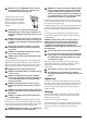
1. Before You Start... If You Smell Gas Thank you for buying a Falcon cooker. It should give you many years of trouble-free cooking if installed and operated correctly. It is important that you read this section before you start, particularly if you have not used a dual fuel cooker before. • • • • • • • This appliance is designed for domestic cooking nn only. Using it for any other purpose could invalidate any warranty or liability claim.
When the oven is on, DO NOT leave the oven door nn open for longer than necessary – otherwise, the NEVER leave a chip pan unattended. Always heat fat nn slowly, and watch as it heats. Deep fry pans should Cooking high moisture content foods can create a ‘steam burst’ when the oven door is opened. When opening the oven stand well back and allow any steam to disperse. Foods for frying should be as dry as possible.
2. Cooker Overview DocNo.020-0006 - Overview - 100DF - Prof+ Fig.2-1 A B O 1 1 2 2 3 3 C E M D F ArtNo.212-0019 - 110 DF Classic Deluxe front view The 110 dual fuel cooker (Fig.2-1) has the following features: A. B. C. D. E. F. Fig.2-2 Four hotplate burners with a wok burner and ceramic multizone hotplate A control panel A glide-out grill A multi-function oven A fan oven A storage drawer Hotplate Burners The drawing by each of the central knobs indicates which burner that knob controls.
The igniter should spark and light the gas. Keep holding the knob pressed in to let the gas through to the burner for about ten seconds. Fig.2-3 If, when you let go of the control knob, the burner goes out, then the FSD has not been bypassed. Turn the control knob to the ‘OFF’ position and wait for one minute before you try again, this time making sure to hold in the control knob for slightly longer. Adjust the flame height to suit by turning the knob counterclockwise (Fig.2-3).
The cradle will get very hot in use – allow plenty of time for it to cool before you pick it up. Fig.2-11 The Ceramic Hotplate The hotplate area on the left-hand side is dual purpose. It can be used either as a ceramic hob to heat a pan in the usual way (Fig.2-11) or it can be used to heat the supplied griddle. The rear area, marked with a ring is for cooking with a pan. There are two elements that allow either the whole of the area to be heated or just the rear half.
The Griddle Fig.2-16 The griddle (Fig.2-16) is designed to fit securely on the locating pins over the ceramic heating area (Fig.2-17). Do not try to use it over one of the gas burners. It will not be securely held and you may damage the non-stick finish. There are two elements that allow either the whole of the area to be heated or just the rear half. To heat the whole area, turn the knob clockwise (Fig.2-18). To heat the rear ring only, turn it counter-clockwise (Fig.2-19). Fig.
The Glide-out Grill Fig.2-21 Open the door and pull the grill pan carriage forward using the handle (Fig.2-21). The grill has two elements that allow either the whole area of the pan to be heated or just the right-hand half. To heat the whole grill, turn the control knob clockwise (Fig.2-22). To heat the right-hand half, turn the control knob counterclockwise. The neon indicator light by the grill control will come on. ArtNo.331-0001Grill pan pulled forwards Fig.
Function Use The Ovens Rapid Response To quickly heat up the oven Defrost To thaw small items in the oven without heat The clock must be set to the time of day before the ovens will work. See the following section on ‘The Clock’ for instructions on setting the time of day.
cooking time, as the heat at the top of the oven is greater than at the base, when using this function. Multi-function Oven Functions Rapid Response The Rapid Response setting enables you to preheat the oven faster than normal. It uses the fan oven element with additional heat from one of the elements in the top of the oven. Rangemaster fan ovens heat up quickly; but the Rapid Response feature speeds this process up enabling you to commence cooking sooner.
Right-hand Fan Oven Fig.2-24 The right-hand oven is a fan oven that circulates hot air continuously, which means faster, more even cooking. ArtNo.235-0003 - Classic DL MF knobs The recommended cooking temperatures for a fan oven are generally lower than a conventional oven. Note: Please remember that all cookers vary so temperatures in your new ovens may differ to those in your previous cooker.
The Clock Fig.2-28 You can use the timer to turn the left-hand multi-function oven on and off. The clock must be set to the time of day before the ovens will work. Setting the Time of Day ArtNo.302-0002 - 6BC annotated The 6-button LCD clock is shown in Fig.2-28. When the clock is first connected the display flashes ( 0.00 ) and (G) alternately. A Press and hold both the [C] and [D] buttons down (Fig.2-29). Now press the [+] button (or the [–] button) until the correct time shows.
Fig.2-38 AUTO is Showing, But you Want to Reset to Manual Cooking Fig.2-39 ArtNo.302-0008 Activating the key lock 1 To return to manual cooking from any automatic setting, the ‘cook period’ must be cancelled. Press and hold the [E] button and then press the [–] button until the display reads ( 0.00 ). ArtNo.302-0009 - Activating the key lock 2 Press the [B] button to return to manual cooking. Key Lock Activating the key lock will lock the left-hand oven and it will not come on. Fig.
Accessories Fig.2-43 Oven Shelves Flat shelf Shelf guard In addition to the flat shelves, your cooker is supplied with a drop shelf (Fig.2-43). The drop shelf increases the possibilities for oven shelf spacing. Front The oven shelves can be easily removed and refitted. Pull the shelf forward until the back of the shelf is stopped by the shelf stop bumps in the oven sides (Fig.2-44).
Oven Lights Fig.2-50 Press the button to turn the lights on (Fig.2-50). If the oven light fails, turn off the power supply before changing the bulb. See the ‘Troubleshooting’ section for details on how to change the bulb. ArtNo.320-0017 Main oven light Storage The bottom drawer is for storing oven trays and other cooking utensils. Fig.2-51 It can get very warm, so do not store anything in it that may melt or catch fire. ArtNo.
3. Cooking Tips Tips on Cooking with the Timer General Oven Tips If you want to cook more than one dish, choose dishes that require approximately the same cooking time. However, dishes can be ‘slowed down’ slightly by using small containers and covering them with aluminium foil, or ‘speeded up’ slightly by cooking smaller quantities or placing them in larger containers. The wire shelves should always be pushed firmly to the back of the oven.
4. Cooking Table DocNo.031-0004 - Cooking table - electric & fan single cavity The oven control settings and cooking times given in the table below are intended to be used AS A GUIDE ONLY. Individual tastes may require the temperature to be altered to provide a preferred result. Food is cooked at lower temperature in a fan oven than in a conventional oven. When using recipes, reduce the fan oven temperature by 10 °C and the cooking time by 5-10 minutes.
5. Cleaning Your Cooker Essential Information Fig.5-1 A Isolate the electricity supply before carrying out any thorough cleaning. Allow the cooker to cool. C Never use paint solvents, washing soda, caustic nn cleaners, biological powders, bleach, chlorine based B bleach cleaners, coarse abrasives or salt. Do not mix different cleaning products – they may nn react together with hazardous results.
Ceramic Hotplate Fig.5-5 Daily Care First of all, make sure that the heat indicator light is off and that the cooking surface is cool. Apply a small dab of ceramic cleaning cream in the centre of the area to be cleaned. Dampen a clean paper towel and work the cream onto the cooking surface. As a final step, wipe the cooking surface with a clean, dry paper towel.
Glide-out Grill Fig.5-6 The grill pan and trivet should be washed in hot soapy water. Alternatively, the grill pan can be washed in a dishwasher. After grilling meats or any foods that soil, leave to soak for a few minutes immediately after use. Stubborn particles may be removed from the trivet using a nylon brush. Before you remove any of the grill parts for cleaning, nn make sure that they are cool, or use oven gloves. DO NOT use any abrasive substances. nn ArtNo.
Control Panel and Doors Fig.5-11 Avoid using any abrasive cleaners, including cream cleaners. For best results, use a liquid detergent. The same cleaner can also be used on the doors. Alternatively, use a soft cloth wrung out in clean hot soapy water. You can use the same method for cleaning the control panel and knobs. After cleaning, polish with a dry cloth. Glass Fronted Door Panels The oven door front panels can be taken off so that the glass panels can be cleaned.
Cleaning Table Cleaners listed (Table 5-1) are available from supermarkets or electrical retailers as stated. For enamelled surfaces use a cleaner that is approved for use on vitreous enamel. Regular cleaning is recommended. For easier cleaning, wipe up any spillages immediately. Hotplate Part Finish Recommended Cleaning Method Hob top (including burner heads and caps) Enamel, stainless steel, aluminium Hot soapy water, soft cloth. Any stubborn stains remove gently with a nylon scourer.
6. Troubleshooting Hotplate ignition or hotplate burners faulty Is the power on? Is the clock illuminated? Power failure In the event of a failure in the electrical supply, remember to reset the clock to make sure that the timed oven continues to operate. If not, there maybe something wrong with the power supply. Food is cooking too slowly, too quickly, or burning Cooking times may differ from your previous oven.
An oven light is not working The bulb has probably burnt out. You can buy a replacement bulb (which is not covered under the warranty) from a good electrical shop. Ask for a 15 W – 230 V lamp, FOR OVENS. It must be a special bulb, heat resistant to 300 °C (Fig.6-1). Fig.6-1 ArtNo.324-0005 Oven light bulb Turn off the power at the circuit breaker. Before removing the existing bulb, turn off the power supply and make sure that the oven is cool. Open the oven door and remove the oven shelves. Fig.
INSTALLATION Check the appliance is electrically safe and gas sound when you have finished. 7. Installation Service and Spares Firstly, please complete the appliance details below and keep them safe for future reference – this information will enable us to accurately identify the particular appliance and help us to help you. Filling this in now will save time and inconvenience if you later have a problem with the appliance. It may also be of benefit to keep your purchase receipt with this leaflet.
INSTALLATION Check the appliance is electrically safe and gas sound when you have finished. Dear Installer Provision of Ventilation Before you start your installation, please complete the details below, so that, if your customer has a problem relating to your installation, they will be able to contact you easily. This appliance is not connected to a combustion products evacuation device. Particular attention shall be given to the relevant requirements regarding ventilation.
INSTALLATION Check the appliance is electrically safe and gas sound when you have finished. Checking the parts: Location of Cooker The cooker may be installed in a kitchen/kitchen diner but NOT in a room containing a bath or shower. 3 pan supports This appliance is designed for domestic cooking only. Use for any other purpose could invalidate any warranty or liability claim. Note: An appliance for use on LPG must not be installed in a room or internal space below ground level, e.g. in a basement.
INSTALLATION Check the appliance is electrically safe and gas sound when you have finished. Positioning the Cooker Fig.7-1 Fig.7-1 shows the minimum recommended distance from the cooker to nearby surfaces. 75 mm min 650 mm min The cooker should not be placed on a base. 75 mm min The hotplate surround should be level with, or above, any adjacent work surface. A gap of 75 mm should be left between each side of the cooker ABOVE the hotplate level and any adjacent vertical surface.
INSTALLATION Check the appliance is electrically safe and gas sound when you have finished. Lowering the Two Rear Rollers Fig.7-5 To adjust the height of the rear of the cooker, first fit a 13 mm spanner or socket wrench onto the hexagonal adjusting nut (Fig.7-5). Rotate the nut – clockwise to raise – counterclockwise to lower. Make 10 complete (360°) turns clockwise. Make sure you lower BOTH REAR ROLLERS. Completing the Move Unfold the rear edge of the cardboard base tray.
INSTALLATION Check the appliance is electrically safe and gas sound when you have finished. Repositioning the Cooker Following Connection Fig.7-10 If you need to move the cooker once it has been connected then you need to unplug it and, having gripped under the fascia panel and lifted the front of the cooker slightly (Fig.7-6), you need to check behind the cooker to make sure that the gas hose is not caught. ArtNo.
INSTALLATION Check the appliance is electrically safe and gas sound when you have finished. Gas Connection Fig.7-13 600 350 This must be in accordance with the relevant standards. Position for gas supply connector The flexible hose (not supplied with the cooker) must be in accordance with the relevant standards. Hoses may be purchased at most builders’ merchants. 100 250 The gas supply needs to terminate with a down-facing bayonet.
INSTALLATION Check the appliance is electrically safe and gas sound when you have finished. Electrical Connection Fig.7-14 This appliance must be installed by a qualified electrician to comply with the relevant regulations (AS/NZS 60335.2.6) and also the local electricity supply company requirements. Make sure that the mains characteristics (voltage, nominal, power, etc.) match the ratings indicated on the cooker data plate. ArtNo.
INSTALLATION Check the appliance is electrically safe and gas sound when you have finished. Final Checks Fig.7-18 Hob Check Check each cooking zone in turn. Be sure to use pans of the correct size and material. ArtNo.350-0010 - Fitting the plinth 1 (Kitchener) Grill Check Turn on the grill control and check that the grill heats up. Oven Check Set the clock as described earlier, and then turn on the ovens. Check the oven fan start to turn and that the ovens heat up. Fig.
WARNING – SERVICING TO BE CARRIED OUT ONLY BY AN AUTHORISED PERSON Disconnect from electricity and gas before servicing. Check appliance is safe when you have finished. 8. Conversion to LP Gas Conversion from Natural Gas (1.0 kPa) to LPG X Propane (2.54 kPa) Fig.8-1 This conversion must be performed by a competent nn person, in accordance with these instructions and with the local supply company requirements. Read the instructions before converting this appliance.
WARNING – SERVICING TO BE CARRIED OUT ONLY BY AN AUTHORISED PERSON Disconnect from electricity and gas before servicing. Check appliance is safe when you have finished. Set the Governor Fig.8-5 Unscrew the governor’s brass top. In the base of the brass top is a plastic snap-in converter device (Fig.8-5). To convert the governor, snap the device out of the top and refit it the other way round. The snap-in converter device is marked to show the gas for which it is set (Fig.8-6). ArtNo.
WARNING – SERVICING TO BE CARRIED OUT ONLY BY AN AUTHORISED PERSON Disconnect from electricity and gas supplies before servicing. Check appliance is safe when you have finished. 9. Servicing BEFORE SERVICING ANY GAS CARRYING nn COMPONENTS TURN OFF THE GAS SUPPLY Fig.9-1 ArtNo.210-0009 - Classic removing the handles Check the appliance is gas sound after completion nn of service. When checking for gas leaks DO NOT use washing up liquid – this can corrode.
WARNING – SERVICING TO BE CARRIED OUT ONLY BY AN AUTHORISED PERSON Disconnect from electricity and gas supplies before servicing. Check appliance is safe when you have finished. 2 Fig.9-3 Hotplate 2.1 To Remove the Hotplate Top DISCONNECT FROM THE ELECTRICITY SUPPLY. Caution The ceramic hob material is much more sensitive to scratches on the underside than the top. Take care not to touch or scratch the underside of the ceramic as this will weaken the material and cause the top to shatter.
WARNING – SERVICING TO BE CARRIED OUT ONLY BY AN AUTHORISED PERSON Disconnect from electricity and gas supplies before servicing. Check appliance is safe when you have finished. 3.3 To Remove the Electronic Timer Replace the burner cap. Check the burner ignition. Replace the pan supports. DISCONNECT FROM THE ELECTRICITY SUPPLY. Pull off the timer control button(s) and remove the control panel (see 1.2). Remove the timer/mounting bracket assembly from the control panel by removing the fixing screws.
WARNING – SERVICING TO BE CARRIED OUT ONLY BY AN AUTHORISED PERSON Disconnect from electricity and gas supplies before servicing. Check appliance is safe when you have finished. 5 Fig.9-5 Ovens 5.1 To Replace an Oven Thermostat DISCONNECT FROM THE ELECTRICITY SUPPLY. Remove the handrail (see 1.1), control panel (see 1.2) and hotplate top (see 2.1). Open the oven doors and remove the oven furniture.
WARNING – SERVICING TO BE CARRIED OUT ONLY BY AN AUTHORISED PERSON Disconnect from electricity and gas supplies before servicing. Check appliance is safe when you have finished. 5.2 To Remove an Oven Element Thermal Cut-out Fig.9-7 DISCONNECT FROM THE ELECTRICITY SUPPLY. Pull the cooker forward to gain access to the cover box. Undo the cover screws and lift clear. The cut-out is located on the earth plate beside the oven element connections. Disconnect the cut-out wiring.
WARNING – SERVICING TO BE CARRIED OUT ONLY BY AN AUTHORISED PERSON Disconnect from electricity and gas supplies before servicing. Check appliance is safe when you have finished. 5.6 To Remove the Left-hand Oven Bottom and Top Elements Fig.9-8 DISCONNECT FROM THE ELECTRICITY SUPPLY. ArtNo.322-0002 Oven bottom element access B Bottom Element Pull the cooker forward to access the cover boxes at the rear of the unit. Remove the fixings that secure the cover and lift it clear.
WARNING – SERVICING TO BE CARRIED OUT ONLY BY AN AUTHORISED PERSON Disconnect from electricity and gas supplies before servicing. Check appliance is safe when you have finished. 6.4 To Replace the Main Oven Door Outer Panel Fig.9-13 Move the cooker forwards to gain access to the sides. Open the oven door slightly and remove the 4 front panel fixing screws from the door sides (2 each side), (Fig.9-13). Carefully lift off the outer door panel.
10. Circuit Diagram J r J A1 bk v v 2 P2 1 P1 w B1a w J bk r J v bk r br v v r A2 bk r v I b r gr b B3 br b r I A4 b b b b P8 v 7 P7 r 6 P6 w B2 r r b bk b 4 P4 y 3 P3 G2 2 P2 1 P1 r v y P038434 b br br P5 br b br w bk b r b 1.1kW or b v 8 5 B7 v bk or r B4 B5 B6 b A3 G1 b b bk y bk br r br br br K br br w v C b B1 P095199 bk b b b b b J H1 w w b y 1 D1 2 bk F1 bk v 1.
DocNo.107-0023 - Technical data - 110DF - Classic DL 11. Technical Data This cooker is designed for use on Natural gas, although a conversion for LP (LPG X Propane (2.54 kPa)) gas is packed with the cooker. INSTALLER: Please leave these instructions with the user. DATA BADGE LOCATION: Cooker back. The serial number is repeated on the badge below the left-hand oven door opening. COUNTRY OF DESTINATION: Australia. Connection & Test Pressures Gas (Rp ½ at rear right-hand side) Natural gas 1 kPa Propane 2.
Notes 44
Notes 45
Clarence Street, Royal Leamington Spa, Warwickshire, CV31 2AD, England. Tel: +44 (0) 1926 457400 Fax: +44 (0) 1926 450526 E-mail: consumers@falconappliances.co.