USER GUIDE & INSTALLATION INSTRUCTIONS Classic 90 Dual Fuel Australia U110806-01A
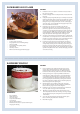
SLOW BAKED LEG OF LAMB METHOD 1. reheat the oven to 220 °C (for a conventional oven), 200 °C (for a P fan oven) or gas mark 7. 2. Pull the small sprigs off the rosemary branches and set aside with the garlic. 3. sing the tip of a paring knife, make up to 20 well-spaced cuts into U the flesh of the lamb, about 2.5 cm inch deep. Divide the rosemary sprigs, garlic and anchovies and push down into the cuts. Place the leg on a large roasting tin and pour over the oil, massaging it all over the joint.
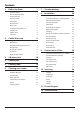
Contents 1. 2. Before You Start... 1 7. Troubleshooting 18 Personal Safety 1 Gas Connection Safety 1 8.
iv
1. Before You Start... • DO NOT spray aerosols in the vicinity of the cooker while it is on. Your cooker should give you many years of trouble-free cooking if installed and operated correctly. It is important that you read this section before you start. Electrical Connection Safety Personal Safety All installations must be in accordance with the relevant instructions in this booklet, with the relevant national and local regulations and with the local electricity supply companies’ requirements.
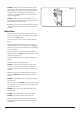
If You Smell Gas Maintenance • DO NOT turn electric switches on or off • Only a qualified service engineer should service the appliance and only approved spare parts should be used. It is recommended that this appliance is serviced annually. • DO NOT smoke • DO NOT use naked flames • Before removing the existing bulb, turn off the power supply and make sure that the oven and bulb have cooled.
• DO NOT use water on grease fires and never pick up a flaming pan. Turn the controls off and then smother a flaming pan on a surface unit by covering the pan completely with a well fitting lid or baking tray. If available, use a multi-purpose dry chemical or foamtype fire extinguisher. Fig. 1.1 • DO NOT modify this appliance. This appliance is not intended to be operated by means of external timer or separated remote-control system. ArtNo.
Grill/Glide-out Grill™ Care Cleaning • When using the grill, make sure that the grill pan is in position and pushed fully in, otherwise the control knobs may become very hot. • Isolate the electricity supply before carrying out any thorough cleaning. Allow the cooker to cool. • In the interests of hygiene and safety, the cooker should be kept clean at all times as a build up in fats and other food stuff could result in a fire.
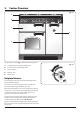
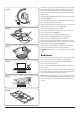
2. Cooker Overview DocNo.020-0006 - Overview - 90DF - Prof+ Fig. 2.1 A B H M G C E D The 90 dual fuel cooker (Fig. 2.1) has the following features: A. 5 hotplate burners including a wok burner B. A control panel incorporating a timer C. A glide-out grill D. Main fan oven E. Tall fan oven Fig. 2.2 Hotplate Burners The drawing by each of the central knobs indicates which burner that knob controls.
If, when you let go of the control knob, the burner goes out, then the FSD has not been bypassed. Turn the control knob to the OFF position and wait for one minute before you try again, this time making sure to hold in the control knob for slightly longer. Fig. 2.3 Adjust the flame height to suit by turning the knob counterclockwise (Fig. 2.3). If a burner flame goes out, turn off the control knob and leave it for one minute before relighting it. Make sure that the flames are under the pans.
The Wok Cradle (optional extra) Fig. 2.9 The wok cradle is designed to fit a 35 cm wok. If you use a different wok, make sure that it fits the cradle. Woks vary very widely in size and shape. It is important that the wok sits down on the pan support – however, if it is too small, the cradle will not support it properly (Fig. 2.9). The cradle should be used on the wok burner only.
The Glide-out Grill Fig. 2.15 CAUTION: Accessible parts may be hot when the grill nn is in use. Young children should be kept away. Open the door and pull the grill pan carriage forward using the handle (Fig. 2.15). The grill has two elements that allow either the whole area of the pan to be heated or just the right-hand half. Adjust the heat to suit by turning the knob. To heat the whole grill, turn the knob clockwise (Fig. 2.16). ArtNo.
The Ovens ArtNo.321-0002 Fan assisted oven The clock must be set to the time of day before the ovens will work. See the following section on ‘The Clock’ for instructions on setting the time of day. Fig. 2.18 References to ‘left-hand’ and ‘right-hand’ ovens apply as viewed from the front of the appliance. The left-hand oven is a programmable fan oven (Fig. 2.18) and the right-hand oven is a tall fan oven (Fig. 2.19). The Fan Oven Fig. 2.
3. 3 Button clock Using the clock Fig. 3.1 You can use the clock to turn the programmable oven on and off. The clock must be set to the time of day before the oven will work. NOTE: When using the timer functions, first set the clock as required before setting the oven temperature. ArtNo.306-0001 - 3-button clock The oven can be switched on when the cook symbol [ ] is displayed. Fig. 3.2 Setting the clock ArtNo.306-0001 - 3-button clock 1. The LCD clock is shown in (Fig. 3.1).
3. When the ‘stop time’ is reached an alarm will sound and the oven will stop working. The word ‘AUTO’ will flash on the display (Fig. 3.6). 4. Press any button to stop the alarm and return to manual cooking. If the alarm is not stopped, it will stop automatically after 7 minutes. Fig. 3.7 ArtNo.306-0001 - 3-button clock To start and then stop the programmable oven Set the programmable oven to automatically start and stop using a combination of the ‘cook period’ and ‘stop time’. Fig. 3.
4. Cooking tips Tips on cooking with the timer General oven tips If you want to cook more than one dish, choose dishes that require approximately the same cooking time. However, dishes can be ‘slowed down’ slightly by using small containers and covering them with aluminium foil, or ‘speeded up’ slightly by cooking smaller quantities or placing them in larger containers. The wire shelves should always be pushed firmly to the back of the oven.
5. Cooking Table The oven control settings and cooking times given in the table below are intended to be used as a guide only. Individual tastes may require the temperature to be altered to provide a preferred result. Food is cooked at lower temperature in a fan oven than in a conventional oven. When using recipes, reduce the fan oven temperature by 10 °C and the cooking time by 5-10 minutes. The temperature in the fan oven does not vary with height in the oven so you can use any shelf.
6. Cleaning your cooker Essential Information Fig. 6.1 Isolate the electricity supply before carrying out any thorough cleaning. Allow the cooker to cool. A C NEVER use paint solvents, washing soda, caustic nn cleaners, biological powders, bleach, chlorine based B bleach cleaners, coarse abrasives or salt. DO NOT mix different cleaning products – they may nn react together with hazardous results.
The Griddle Fig. 6.5 Always clean the griddle after use. Allow it to cool completely before removing. Immerse the griddle plate in hot soapy water. Use a soft cloth or, for stubborn stains, a nylon washing up brush. ArtNo.331-0003 Grill frame out, no pan NOTE: If the griddle is washed in a dishwasher then some dishwasher residue may appear on the back. This is normal and will not affect the performance of your griddle. Glide-out Grill Before you remove any of the grill parts for cleaning.
Glass Fronted Door Panels Fig. 6.9 The oven door front panels can be taken off so that the glass panels can be cleaned. Move the cooker forward to gain access to the sides (see the ‘Moving the Cooker’ section under ‘Installation’). Open the oven door slightly and remove the front panel fixing screws from the door sides, two each side (Fig. 6.9). Carefully lift off the outer door panel. The inside face of the glass panels can now be cleaned – take care not to disturb or wet the door insulation. ArtNo.
Cleaning table Cleaners listed are available from supermarkets or electrical retailers as stated. For enamelled surfaces use a cleaner that is approved for use on vitreous enamel. Regular cleaning is recommended. For easier cleaning, wipe up any spillages immediately. Hotplate Part Finish Recommended Cleaning Method Hob top (including burner heads and caps) Enamel, stainless steel, aluminium Hot soapy water, soft cloth. Any stubborn stains remove gently with a nylon scourer.
7. Troubleshooting Hotplate/Cooktop ignition or hotplate burners faulty Food is cooking too slowly, too quickly, or burning Is the power on? Is the clock illuminated? Cooking times may differ from your previous oven. If not, there maybe something wrong with the power supply. Check that you are using the recommended temperatures and shelf positions – see the oven cooking guide. The oven control settings and cooking times are intended to be used only as a guide.
Oven light is not working Fig. 7.1 ArtNo.324-0005 Oven light bulb The bulb has probably burnt out. You can buy a replacement bulb (which is not covered under the warranty) from a good electrical shop. Ask for a 15 W – 230 V lamp, FOR OVENS. It must be a special bulb, heat resistant to 300 °C (Fig. 7.1). Turn off the power at the circuit breaker. Before removing the existing bulb, turn off the power supply and make sure that the oven is cool. Open the oven door and remove the oven shelves. Fig. 7.
INSTALLATION Check the appliance is electrically safe and gas sound when you have finished. 8. Installation Service and Spares Firstly, please complete the appliance details below and keep them safe for future reference – this information will enable us to accurately identify the particular appliance and help us to help you. Filling this in now will save time and inconvenience if you later have a problem with the appliance. It may also be of benefit to keep your purchase receipt with this leaflet.
INSTALLATION Check the appliance is electrically safe and gas sound when you have finished. Safety Requirements and Regulations Provision of Ventilation Please read the Before you start... chapter, before you begin any installation and maintenance work on this appliance. nn This appliance is not connected to a combustion products evacuation device. Particular attention shall be given to the relevant requirements regarding ventilation.
INSTALLATION Check the appliance is electrically safe and gas sound when you have finished. You will need the following equipment to complete the cooker installation satisfactorily: • • • Checking the Parts: 3 pan supports Flexible gas hose. Gas pressure tester/manometer. Multimeter: For electrical checks. You will also need the following tools: Restraining chain & hook ArtNo.020-0021 - Restraining chain & hook 1. 2.
INSTALLATION Check the appliance is electrically safe and gas sound when you have finished. Positioning the Cooker Fig. 8.1 The diagram (Fig. 8.1) shows the minimum recommended distance from the cooker to nearby surfaces as given in AS/NZS 5601. Where the appliance is installed next to cabinetry, the cabinet material must be capable of withstanding 70°C. If this appliance is installed near vinyl wrapped surfaces, use an installation kit available from the vinyl-wrap supplier.
INSTALLATION Check the appliance is electrically safe and gas sound when you have finished. Moving the Cooker Fig. 8.3 On no account try and move the cooker while it is nn plugged into the electricity supply. The cooker is very heavy, so take great care. nn We recommend that two people manoeuvre the cooker. Make sure that the floor covering is firmly fixed, or removed, to prevent it being disturbed when moving the cooker around.
INSTALLATION Check the appliance is electrically safe and gas sound when you have finished. Levelling Fig. 8.6 You are recommended to use a spirit level on a shelf in one of the ovens to check for level. Place the cooker in its intended position taking care not to twist it within the gap between the kitchen units as damage may occur to the cooker or the units. Alternative positions for stability location bracket The front feet and rear rollers can be adjusted to level the cooker.
INSTALLATION Check the appliance is electrically safe and gas sound when you have finished. Gas Connection Fig. 8.10 Pipework Must be in accordance with the relevant standards. Pipework The gas supply needs to terminate with a side-facing threaded fitting ½” connection. The inlet connector is located just below the hotplate level at the rear of the cooker. Flexible hose Flexible hose Fig. 8.
INSTALLATION Check the appliance is electrically safe and gas sound when you have finished. Electrical Connection Fig. 8.12 This appliance must be installed by a qualified electrician to comply with with current AS/NZS 3000 Wiring Rules and regulations in force. Make sure that the mains characteristics (voltage, nominal, power, etc.) match the ratings indicated on the data plate affixed to the cooker. ArtNo.
INSTALLATION Check the appliance is electrically safe and gas sound when you have finished. Fixed Wiring Fig. 8.14 Disconnect from the mains supply. nn For connection to fixed wiring, i.e. flexible conduit, remove the electrical terminal cover box on the back panel (Fig. 8.14). Fit the conduit box to the cooker using the two M5 screw fittings located at the top of the box. Remove the M4 screw from the base, and fix to the cooker, via the fitting through the back of the conduit box (Fig. 8.15).
INSTALLATION Check the appliance is electrically safe and gas sound when you have finished. Final Checks Fig. 8.18 Note: The clock must be set before the ovens will work. See ‘The Clock’ section for instructions on setting the time of day. Hotplate Check Check each burner in turn. There is a Flame Supervision Device (FSD) that stops the flow of gas to the burner if the flame goes out. For each burner, turn the control knob to the solid flame symbol. Press in the control knob.
WARNING – SERVICING TO BE CARRIED OUT ONLY BY AN AUTHORISED PERSON Disconnect from electricity and gas before servicing. Check appliance is safe when you have finished. 9. Conversion to LP Gas Conversion from Natural Gas (1.0 kPa) to LPG X Propane (2.54 kPa) Fig. 9.1 A suitably competent person must perform the nn conversion. After conversion the installation must comply with the relevant regulations and also the local electricity supply company requirements.
WARNING – SERVICING TO BE CARRIED OUT ONLY BY AN AUTHORISED PERSON Disconnect from electricity and gas before servicing. Check appliance is safe when you have finished. Set the Governor Fig. 9.4 Unscrew the governor’s brass top. In the base of the brass top is a plastic snap-in converter device (Fig. 9.4). To convert the governor, snap the device out of the top and refit it the other way round. The snap-in converter device is marked to show the gas for which it is set (Fig. 9.5). ArtNo.
WARNING – SERVICING TO BE CARRIED OUT ONLY BY AN AUTHORISED PERSON Disconnect from electricity before servicing. Check appliance is safe when you have finished. 10. Servicing BEFORE SERVICING ANY GAS CARRYING nn COMPONENTS TURN OFF THE GAS SUPPLY Fig. 10.1 Check the appliance is gas sound after completion nn of service. When checking for gas leaks DO NOT use washing up liquid – this can corrode. Use a product specifically manufactured for leak detection.
WARNING – SERVICING TO BE CARRIED OUT ONLY BY AN AUTHORISED PERSON Disconnect from electricity before servicing. Check appliance is safe when you have finished. 2.3 To Change a Hotplate Burner Injector 2 Hotplate Remove the burner cap and head. Remove the old injector. BEFORE SERVICING ANY GAS CARRYING nn COMPONENTS, TURN OFF THE GAS SUPPLY. Fit the new injector. Reassemble in reverse order. Check the appliance is gas sound. 2.1 To Remove the Hotplate 2.
WARNING – SERVICING TO BE CARRIED OUT ONLY BY AN AUTHORISED PERSON Disconnect from electricity before servicing. Check appliance is safe when you have finished. 3 Controls 4 Grill 3.1. To Replace the Ignition or Light Switch 4.1 To Replace the Grill Controller DISCONNECT FROM THE ELECTRICITY SUPPLY. DISCONNECT FROM THE ELECTRICITY SUPPLY. Remove the control panel (see 1.1). Remove the control panel and hotplate (see 1.1 & 2.1). Disconnect the wiring from controller.
WARNING – SERVICING TO BE CARRIED OUT ONLY BY AN AUTHORISED PERSON Disconnect from electricity before servicing. Check appliance is safe when you have finished. Fit the new fan and reassemble in reverse order. Check the operation of the oven. Fig. 10.4 5.3 To Change the Oven Element DISCONNECT FROM THE ELECTRICITY SUPPLY. Remove the oven inner back (see 5.1). Remove the 2 screws from the top of the element and the 1 from the bottom of the element (Fig. 10.5).
WARNING – SERVICING TO BE CARRIED OUT ONLY BY AN AUTHORISED PERSON Disconnect from electricity before servicing. Check appliance is safe when you have finished. Fig. 10.6 6 Doors Fig. 10.7 6.1 To Remove the Grill Door Remove the left-hand side panel (see 1.2). Remove the plinth (4 screws) and the central vertical cover (5 screws). Remove the 2 countersunk screws (1 each side) securing the grill hinge arms to the front of the grill chamber. 2 1 ArtNo.320-0001 Door hinges Fig. 10.8 ArtNo.
WARNING – SERVICING TO BE CARRIED OUT ONLY BY AN AUTHORISED PERSON Disconnect from electricity before servicing. Check appliance is safe when you have finished. 6.7 To Remove the Tall Oven Door Fig. 10.13 Open the oven door. Supporting the door, remove the 2 screws securing the upper hinge and packing to the cooker front. Remove the door from the lower hinge by lifting slightly and moving outwards. Reassemble in reverse order. 6.
11.
12. Technical Data ArtNo.105-0008 - Technical data - 90 induction - Elan This cooker is designed for use on Natural gas, although a conversion for LP (LPG X Propane (2.54 kPa)) gas is packed with the cooker. INSTALLER: Please leave these instructions with the User. DATA BADGE LOCATION : Cooker back, serial number repeater badge below oven door opening. COUNTRY OF DESTINATION: Australia. Connection & Test Pressures Gas (Rp ½ at rear right-hand side) Natural Gas Propane Electric 1 kPa 230 V 50 Hz 2.
Clarence Street, Royal Leamington Spa, Warwickshire, CV31 2AD, England. Tel: +44 (0) 800 804 6261 | +44 (0) 370 789 5107 E-mail: consumers@falconappliances.co.