USER GUIDE & INSTALLATION INSTRUCTIONS Elise 90 Dual Fuel Australia U111315 - 01
Contents 1. 2. 1 7. Troubleshooting 21 Personal Safety 1 Electrical Connection Safety 2 8. Service and Spares 23 If You Smell Gas 2 9.
ii
1. Before You Start... Your cooker should give you many years of trouble-free cooking if installed and operated correctly. It is important that you read this section before you start. Personal Safety This appliance is for cooking purposes only. It must not be used for other purposes, for example heating a room. Using it for any other purpose could invalidate any warranty or liability claim. Besides invalidating claims this wastes fuel and may overheat the control knobs.
• DO NOT use a steam cleaner on your cooker. • Always keep combustible materials, e.g. curtains, and flammable liquids a safe distance away from the cooker. • Make sure that the gas supply is turned on and that the cooker is wired in and switched on. • DO NOT spray aerosols in the vicinity of the cooker while it is on. • In your own interest and that of safety, it is law that all gas appliances be installed by a qualified person(s).
by the manufacturer of the cooking appliance or indicated by the manufacturer of the appliance in the instructions for use as suitable or hob guards incorporated in the appliance. The use of inappropriate guards can cause accidents. the grill or ovens are in operation the fan will run to cool the fascia and control knobs. Ventilation The use of a cooking appliance results in the production of heat and moisture in the room in which it is installed.
along the back of the cooker) for warming plates, dishes, drying tea towels or softening butter. Fig. 1.1 • DO NOT use water on grease fires and never pick up a flaming pan. Turn the controls off and then smother a flaming pan on a surface unit by covering the pan completely with a well fitting lid or baking tray. If available, use a multi-purpose dry chemical or foam-type fire extinguisher. • DO NOT modify this appliance.
underneath it, otherwise the knobs may become hot. door glass since they can scratch the surface, which may result in shattering of the glass. • Make sure the shelves are pushed firmly to the back of the oven. DO NOT close the door against the oven shelves. • DO NOT use aluminium foil to cover shelves, linings or the oven roof. • When the oven is on, DO NOT leave the oven door open for longer than necessary, otherwise the control knobs may become very hot.
6 • Before you remove any of the grill parts for cleaning, make sure that they are cool or use oven gloves. • DO NOT use any abrasive substances on the grill and grill parts. • DO NOT put the side runners in a dishwasher. • DO NOT put the burner heads in a dishwasher. • NEVER use caustic or abrasive cleaners as these will damage the surface. • DO NOT use steel wool, oven cleaning pads or any other materials that will scratch the surface. • NEVER store flammable materials in the drawer.
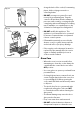
2. Range Overview DocNo.020-0006 - Overview - 100DF - Prof+ Fig. 2.1 A B C E D The 90 dual fuel cooker (Fig. 2.1) has the following features: A. Four hotplate burners with one wok burner B. Control Panel C. Glide-Out Grill™ D. Multifunction Oven E. Tall Fan Oven 0 Hotplate Burners The drawing by each of the central knobs indicates which burner that knob controls. Each burner has a Flame Supervision Device (FSD) that prevents the flow of gas if the flame goes out.
Fig. 2.3 The igniter should spark and light the gas. Keep holding the knob pressed in to let the gas through to the burner for about ten seconds. 0 If, when you let go of the control knob, the burner goes out, then the FSD has not been bypassed. Turn the control knob to the OFF position and wait for one minute before you try again, this time making sure to hold in the control knob for slightly longer. Adjust the flame height to suit by turning the knob counterclockwise (Fig. 2.3).
The Wok Cradle Fig. 2.9 The wok cradle is designed to fit a 35 cm wok. If you use a different wok, make sure that it fits the cradle. Woks vary very widely in size and shape. It is important that the wok sits down on the pan support – however, if the wok is too small, the cradle will not support it properly (Fig. 2.9). The cradle should be used on the wok burners only. When you fit the cradle, check that it is supported properly on a pan support and the wok is sitting level in the cradle (Fig. 2.10).
The Glide-out Grill™ (Fig. 2.14) Fig. 2.
The Fan Oven Fig. 2.15 The right-hand oven is a fan oven that circulates hot air continuously, which means faster, more even cooking. 0 The recommended cooking temperatures for a fan oven are generally lower than a conventional oven. NOTE: Please remember that all cookers vary so temperatures in your new ovens may differ to those in your previous cooker. 100 220 180 140 Operating the Ovens Fan Oven Fig. 2.16 Turn the oven knob to the desired temperature (Fig. 2.15).
Multifunction Oven Functions Conventional Oven (Top and Base Heat) This function combines the heat from the top and base elements. It is particularly suitable for roasting and baking pastry, cakes and biscuits. Fan Oven This function operates the fan and the heating element around it. An even heat is produced throughout the oven, allowing you to cook large amounts quickly.
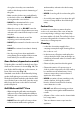
Accessories Shelf guard Fig. 2.19 Oven Shelves – Left-hand (Main) Oven The oven shelves (Fig. 2.19) can be easily removed and refitted. Pull the shelf forward until the back of the shelf is stopped by the shelf stop bumps in the oven sides (Fig. 2.20). Front Lift up the front of the shelf so the back of the shelf will pass under the shelf stop and then pull the shelf forward (Fig. 2.21). Fig. 2.
3. Using the Glide-out Grill™ DocAUS.020-0004 - Overview - 110DF - Elan Fig. 3.2 Fig. 3.1 Nearest to the element Middle High Middle Low Furthest from the element Four grill height positions refer to Fig. 3.5 Fig. 3.4 Fig. 3.3 1 0 1 2 1 2 3 0 1 2 3 2 3 3 To switch on both elements To switch on the right half element Fig. 3.5 Four grill height positions Nearest to the element Middle High 180o Cooking suggestions Furthest from the element 180o Middle Low 180o 180o 1.
English 4. Cooking tips Cooking with a multifunction oven General oven tips Remember: not all modes are suitable for all food types. The oven cooking times given are intended for a guide only. The wire shelves should always be pushed firmly to the back of the oven. Baking trays with food cooking on them should be placed level with the front edge of the oven’s wire shelves. Other containers should be placed centrally.
5. Cooking Table The oven control settings and cooking times given in the table below are intended to be used as a guide only. Individual tastes may require the temperature to be altered to provide a preferred result. Food is cooked at lower temperature in a fan oven than in a conventional oven. When using recipes, reduce the fan oven temperature by 10 °C and the cooking time by 5-10 minutes. The temperature in the fan oven does not vary with height in the oven so you can use any shelf.
6. Cleaning your cooker Essential information Fig. 6.1 Isolate the electricity supply before carrying out any thorough cleaning. Allow the cooker to cool. n n A C NEVER use paint solvents, washing soda, caustic cleaners, biological powders, bleach, chlorine based bleach cleaners, coarse abrasives or salt. B DO NOT mix different cleaning products – they may react together with hazardous results.
Fig. 6.5 The Griddle (optional) ArtNo.331-0003 Grill frame out, no pan Always clean the griddle after use. Allow it to cool completely before removing. Immerse the griddle plate in hot soapy water. Use a soft cloth or, for stubborn stains, a nylon washing up brush. NOTE: If the griddle is washed in a dishwasher then some dishwasher residue may appear on the back. This is normal and will not affect the performance of your griddle.
Glass fronted door panels Fig. 6.8 The oven door front panels can be taken off so that the glass panels can be cleaned. Move the cooker forward to gain access to the sides (see the ‘Moving the Cooker’ section under ‘Installation’). Open the oven door slightly and remove the front panel fixing screws from the door sides, two each side (Fig. 6.8). Carefully lift off the outer door panel. The inside face of the glass panels can now be cleaned – take care not to disturb or wet the door insulation. ArtNo.
Cleaning table Cleaners listed are available from supermarkets or electrical retailers as stated. For enamelled surfaces use a cleaner that is approved for use on vitreous enamel. Regular cleaning is recommended. For easier cleaning, wipe up any spillages immediately. Hotplate Part Finish Recommended Cleaning Method Hob top (including burner heads and caps) Enamel, stainless steel, aluminium Hot soapy water, soft cloth. Any stubborn stains remove gently with a nylon scourer.
7. Troubleshooting Hotplate/Cooktop ignition or hotplate burners faulty Food is cooking too slowly, too quickly, or burning Is the power on? Is the clock illuminated? Cooking times may differ from your previous oven. If not, there maybe something wrong with the power supply. Check that you are using the recommended temperatures and shelf positions – see the oven cooking guide. The oven control settings and cooking times are intended to be used only as a guide.
Oven light is not working Fig. 7.1 The bulb has probably burnt out. You can buy a replacement bulb (which is not covered under the warranty) from a good electrical shop. Ask for 40 W - 230 V halogen lamp (G9) (Fig. 7.1). Turn off the power at the circuit breaker. Before removing the existing bulb, turn off the power supply and make sure that the oven is cool. Open the oven door and remove the oven shelves. Fig. 7.2 Remove the bulb cover by turning it a quarter turn, counterclockwise.
INSTALLATION Check the appliance is electrically safe when you have finished. 8. Service and Spares Firstly, please complete the appliance details below and keep them safe for future reference – this information will enable us to accurately identify the particular appliance and help us to help you. Filling this in now will save time and inconvenience if you later have a problem with the appliance. It may also be of benefit to keep your purchase receipt with this leaflet.
INSTALLATION Check the appliance is electrically safe and gas sound when you have finished. 9. Installation Location of range Checking the parts: The range may be installed in a kitchen/kitchen diner but NOT in a room containing a bath or shower. 3 pan supports This appliance is designed for domestic cooking only. Use for any other purpose could invalidate any warranty or liability claim. Wok cradle ArtNo.
INSTALLATION Check the appliance is electrically safe and gas sound when you have finished. Positioning the Range Fig. 9.1 The diagram (Fig. 10.1) shows the minimum recommended distance from the range to nearby surfaces as given in AS/NZS 5601. Overhead – Measurement A 0 0 1 2 0 0 0 0 0 0 0 2 100 220 3 100 220 140 3 Trivet Side Clearances – Measurements B & C ArtNo.
INSTALLATION Check the appliance is electrically safe and gas sound when you have finished. When Fitting Between Kitchen Cabinets Fig. 9.4 *Note 5mm gap if the appliance is 30mm in front of the kitchen cabinets 9mm gap if the appliance is to be flush fitted between kitchen cabinets WORKTOP DOOR CHROME TRIM DOOR HANDLE We recommend that you either: A. Fit the range so that any cabinet doors are at least 30 mm behind the range door fronts. Note that this may require an infill piece behind the range.
INSTALLATION Check the appliance is electrically safe and gas sound when you have finished. Completing the move Fig. 9.6 Unfold the rear edge of the cardboard base tray. Open the oven door(s) so that you can get a good grip on the bottom of the fascia panel as you move the oven (Fig. 9.6). Carefully push the range backwards off the base tray. Remove the base tray. Position the range close to its final position, leaving just enough space to get behind it (Fig. 9.7). n ArtNo.
INSTALLATION Check the appliance is electrically safe and gas sound when you have finished. Repositioning the range following connection Fig. 9.12 675 Gas inlet 315 If you need to move the range once it has been connected then you need to unplug it and, having gripped under the fascia panel and lifted the front of the range slightly (Fig. 9.6), you need to check behind the range to make sure that the gas hose is not caught.
INSTALLATION Check the appliance is electrically safe and gas sound when you have finished. Pressure Testing Current Operated Earth Leakage Breakers The pressure test point is accessible on the inlet pipe at the rear. Remove the test nipple screw and fit a pressure gauge to the test point. Turn on and light two of the hotplate burners.
INSTALLATION Check the appliance is electrically safe and gas sound when you have finished. Connection in New Zealand Fig. 9.15 Type of cord in accordance with IEC 60227 with a minimum rating of 90°C. Cord size recommended for this application is 3 x 10 mm², three-core cable (Power cables may be sized to take into account the coincidence factor AS/NZS 60335.2.6:2014). Rating of the plug is 32 Amp, in accordance with AS/NZS 3112.
INSTALLATION Check the appliance is electrically safe when you have finished. 10. Final Fitting Fitting the Handrail 1. Using the 2 mm Allen key supplied, loosen the two retaining screws in the base and side of the handrail support. Fit the handrail support onto the locating bosses on the fascia (Fig. 10.1). Retaining screw Fig. 10.1 NOTE: The handle support should face upwards. 2. Push the support back against the fascia and tighten the one retaining screws. Repeat for the other side.
WARNING – SERVICING TO BE CARRIED OUT ONLY BY AN AUTHORISED PERSON Disconnect from electricity and gas before servicing. Check appliance is safe when you have finished. 11. Conversion to LP Gas Conversion from Natural Gas (1.0 kPa) to LPG X Propane (2.54 kPa) n n Fig. 11.1 A suitably competent person must perform the conversion. After conversion the installation must comply with the relevant regulations and also the local electricity supply company requirements.
WARNING – SERVICING TO BE CARRIED OUT ONLY BY AN AUTHORISED PERSON Disconnect from electricity and gas before servicing. Check appliance is safe when you have finished. Set the Governor Fig. 11.5 Unscrew the governor’s brass top. In the base of the brass top is a plastic snap-in converter device (Fig. 11.5). To convert the governor, snap the device out of the top and refit it the other way round. The snap-in converter device is marked to show the gas for which it is set (Fig. 11.6). ArtNo.
WARNING – SERVICING TO BE CARRIED OUT ONLY BY AN AUTHORISED PERSON Disconnect from electricity before servicing. Check appliance is safe when you have finished. 12. Servicing Fig. 12.1 n BEFORE SERVICING ANY GAS CARRYING COMPONENTS TURN OFF THE GAS SUPPLY n Check the appliance is gas sound after completion of service. When checking for gas leaks do not use washing up liquid – this can corrode. Use a product specifically manufactured for leak detection.
WARNING – SERVICING TO BE CARRIED OUT ONLY BY AN AUTHORISED PERSON Disconnect from electricity before servicing. Check appliance is safe when you have finished. 2 Hotplate Fig. 12.3 2.1 To remove the hotplate n BEFORE SERVICING ANY GAS CARRYING COMPONENTS, TURN OFF THE GAS SUPPLY. n DISCONNECT FROM THE ELECTRICAL SUPPLY ! Screws Remove the pan supports and burner heads. Remove the screws holding the hotplate burners to the hotplate Fig. 12.
WARNING – SERVICING TO BE CARRIED OUT ONLY BY AN AUTHORISED PERSON Disconnect from electricity before servicing. Check appliance is safe when you have finished. 2.5 To Replace a Hotplate Burner n DISCONNECT FROM THE ELECTRICITY SUPPLY. Remove the hotplate tray (see 2.1). The burners (except the wok burner) are mounted on support struts. For these burners, disconnect the burner feed pipes at the burner. Remove the screws at the front and rear holding the support struts. Lift the strut and burners clear.
WARNING – SERVICING TO BE CARRIED OUT ONLY BY AN AUTHORISED PERSON Disconnect from electricity before servicing. Check appliance is safe when you have finished. 4 Grill Fig. 12.6 4.1 To Replace the Grill Controller n DISCONNECT FROM THE ELECTRICITY SUPPLY. Remove the control panel and hotplate (see 1.1 & 2.1). Disconnect the wiring from controller. Remove the 2 screws holding the controller to the mounting panel. Fit the new controller and reassemble in the reverse order. Check for correct operation.
WARNING – SERVICING TO BE CARRIED OUT ONLY BY AN AUTHORISED PERSON Disconnect from electricity before servicing. Check appliance is safe when you have finished. Tall Oven Fig. 12.7 Open the tall oven door and remove the 2 lower screws and washers and remove the upper screw and washer securing the inner back to the back of the oven (Fig. 12.7). Carefully lift away the inner back. Reassemble in reverse order, making sure that you fully tighten the 3 screws and washers. 5.
WARNING – SERVICING TO BE CARRIED OUT ONLY BY AN AUTHORISED PERSON Disconnect from electricity before servicing. Check appliance is safe when you have finished. it clear. Fig. 12.11 Remove the 2 screws ‘A’ and allow the plate to drop down (Fig. 12.9). Remove the 2 screws ‘B’, lower the upper plate and remove through the slot in the cooker back (Fig. 12.10). Fig. 12.12 Undo the terminal connections, noting their positions. Remove the element fixings and withdraw the element.
WARNING – SERVICING TO BE CARRIED OUT ONLY BY AN AUTHORISED PERSON Disconnect from electricity before servicing. Check appliance is safe when you have finished. 6.5 To Change the Left Hand Oven Door Latch Fig. 12.17 Fig. 12.16 Remove the outer door panel (see 6.4). Remove screws ‘B’, which hold the latch assembly to the inner door panel (Fig. 12.16). Fit the new catch and reassemble in reverse order. Check the door operation. ArtNo.320-0004 Oven door keep 6.
13.
14. Technical Data This cooker is designed for use on Natural Gas, although a conversion for LP (LPG X Propane (2.54 kPa)) gas is included. INSTALLER: Please leave these instructions with the user. DATA BADGE LOCATION: Cooker back, serial number repeater badge below oven door opening. COUNTRY OF DESTINATION: Australia.
NOTE 43
Clarence Street, Royal Leamington Spa, Warwickshire, CV31 2AD, England. www.falconworld.