LEIHDC90BB-EU LEIHDC90BC-EU LEIHDC90SC-EU FALHDC90BB FALHDC90BC LEIHDC110BB-EU LEIHDC110BC-EU LEIHDC110SC-EU FALHDC110BB FALHDC110BC RMHDC110WC/-EU LEIHDC120BB-EU LEIHDC120BC-EU LEIHDC120SC-EU FALHDC120BB FALHDC120BC FALHDC90CR/C FALHDC110CR/C FALHDC90CY/C FALHDC110CY/C Libretto di Istruzioni Instructions Manual Manuel d’Instructions Bedienungsanleitung Gebruiksaanwijzing Manual de instrucciones Manual de Instruções
INDICE IT CONSIGLI E SUGGERIMENTI ..............................................................................................................................................4 CARATTERISTICHE ..............................................................................................................................................................5 INSTALLAZIONE...............................................................................................................................................
ÍNDICE PT CONSELHOS E SUGESTÕES ............................................................................................................................................46 CARACTERÍSTICAS ............................................................................................................................................................47 INSTALAÇÃO .....................................................................................................................................................
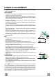
CONSIGLI E SUGGERIMENTI Questo libretto di istruzioni per l'uso è previsto per più versioni dell' apparecchio. É possibile che siano descritti singoli particolari della dotazione, che non riguardano il Vostro apparecchio. INSTALLAZIONE • Il produttore declina qualsiasi responsabilità per danni dovuti ad installazione non corretta o non conforme alle regole dell’arte.
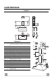
CARATTERISTICHE Ingombro 80 90 4 0 240 465 min.495 max. 770 132 598 - 898 - 1098 - 1198 100 Min. Min. 650mm 650mm 205 490 210 150 Componenti Q.tà Componenti di Prodotto 1 Corpo Cappa completo di: Comandi, Luce, Filtri, Motore 2 1 Camino Telescopico formato da: 2.1 1 Camino Superiore 2.2 1 Camino Inferiore 8a 1 Griglia direzionata Destra 8b 1 Griglia direzionata Sinistra 9 1 Flangia di Riduzione ø 150-120 mm 10 1 Anello di Maggiorazione ø 120-125 mm 15 1 Raccordouscita Aria Rif. Q.
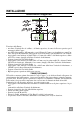
INSTALLAZIONE 1÷2 Foratura Parete e Fissaggio Staffe 190 109,5 109,5 H 650 min. 7.1 X 7.2.1 Tracciare sulla Parete: • una linea Verticale fino al soffitto o al limite superiore, al centro della zona prevista per il montaggio della Cappa; • una linea Orizzontale a: 650 mm min. sopra il Piano di Cottura, per installazione senza Fondale; alla quota H (H=altezza della parte in vista del Fondale), per installazione con Fondale. • Appoggiare come indicato la Staffa 7.2.
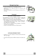
Montaggio Corpo Cappa 12.d • Avvitare sulle Staffe 7.1, le 2 Viti 12d in dotazione. • Agganciare il Corpo Cappa alle Staffe 7.1, centrandolo sulla linea verticale. • Agire sulle Viti 12d, dal sotto della Cappa, per livellare il Corpo Cappa. 7.1 Connessioni USCITA ARIA VERSIONE ASPIRANTE Per installazione in Versione Aspirante collegare la Cappa alla tubazione di uscita per mezzo di un tubo rigido o flessibile di ø150 o 125 mm, la cui scelta è lasciata all'installatore.
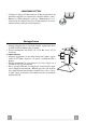
CONNESSIONE ELETTRICA • Collegare la Cappa all’Alimentazione di Rete interponendo un Interruttore bipolare con apertura dei contatti di almeno 3 mm. • Rimuovere i Filtri antigrasso (vedi par. “Manutenzione”) e assicurarsi che il connettore del Cavo di alimentazione sia correttamente inserito nella presa dell’Aspiratore Montaggio Camino Camino superiore • Allargare leggermente le due falde laterali, agganciarle dietro le Staffe 7.2.1 e richiuderle fino a battuta.
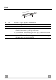
USO 3 1 2 0 1 0 1 V L M L Luci Accende e spegne l’Impianto di Illuminazione. M Motore Accende e spegne il motore Aspirazione. V Velocità Determina la velocità di esercizio: 1. Velocità minima, adatta ad un ricambio d’aria continuo particolarmente silenzioso,in presenza di pochi vapori di cottura. 2. Velocità media, adatta alla maggior parte delle condizioni d’uso, dato l’ottimo rapporto tra portata d’aria trattata e livello sonoro. 3.
MANUTENZIONE Filtri antigrasso PULIZIA FILTRI ANTIGRASSO METALLICI AUTOPORTANTI • Sono lavabili anche in lavastoviglie, e necessitano di essere lavati ogni 2 mesi circa di utilizzo o più frequentemente, per un uso particolarmente intenso. • Togliere i Filtri uno alla volta, spingendoli verso la parte posteriore del gruppo e tirando contemporaneamente verso il basso. • Lavare i Filtri evitando di piegarli, e lasciarli asciugare prima di rimontarli.
RECOMMENDATIONS AND SUGGESTIONS The Instructions for Use apply to several versions of this appliance. Accordingly, you may find descriptions of individual features that do not apply to your specific appliance. INSTALLATION • The manufacturer will not be held liable for any damages resulting from incorrect or improper installation.
CHARACTERISTICS Dimensions 80 90 4 0 240 465 min.495 max. 770 132 598 - 898 - 1098 - 1198 100 Min. Min. 650mm 650mm 205 490 210 150 Components Ref. Q.ty Product Components 1 1 Hood Body, complete with: Controls, Light, Blower, Filters 2 1 Telescopic Chimney comprising: 2.1 1 Upper Section 2.2 1 Lower Section 8a 1 Right Air Outlet Grill 8b 1 Left Air Outlet Grill 9 1 Reducer Flange ø 150-120 mm 10 1 Adapting ring ø 120-125 mm 15 1 Air Outlet Connection Ref. Q.ty Installation Components 7.
INSTALLATION 1÷2 Wall drilling and bracket fixing 190 109,5 109,5 H 650 min. 7.1 X 7.2.1 Wall marking: • Draw a vertical line on the supporting wall up to the ceiling, or as high as practical, at the centre of the area in which the hood will be installed. • Draw a horizontal line at 650 mm above the hob for installation without the back panel, or at height H (height of the visible part of the panel) for installation with the back panel. • Place bracket 7.2.
Mounting the hood body 12.d • Screw the two screws 12d supplied onto the brackets 7.1. • Hook the hood body onto the bracket 7.1, centring it around the vertical line. • Use the adjusting screws 12d underneath the hood to level the hood body. 7.1 Connections DUCTED VERSION AIR EXHAUST SYSTEM When installing the ducted version, connect the hood to the chimney using either a flexible or rigid pipe ø 150 or 125 mm, the choice of which is left to the installer.
ELECTRICAL CONNECTION • Connect the hood to the mains through a two-pole switch having a contact gap of at least 3 mm. • Remove the grease filters (see paragraph Maintenance) being sure that the connector of the feeding cable is correctly inserted in the socket placed on the side of the fan. Chimney assembly Upper chimney section • Slightly widen the two sides of the upper chimney and hook them behind the brackets 7.2.1, making sure that they are properly housed.
USE 3 1 2 0 1 0 1 V L M L Light Switches the lighting system on and off M Motor Switches the extractor motor on and off V Speed Sets the operating speed of the extractor: 1. Low speed, used for a continuous and silent air change in the presence of light cooking vapour. 2. Medium speed, suitable for most operating conditions given the optimum treated air flow/noise level ratio. 3. Maximum speed, used for eliminating the highest cooking vapour emission, including long periods.
MAINTENANCE Grease filters CLEANING METAL SELF- SUPPORTING GREASE FILTERS • The filters must be cleaned every 2 months of operation, or more frequently for particularly heavy usage, and can be washed in a dishwasher. • Remove the filters one at a time by pushing them towards the back of the group and pulling down at the same time. • Wash the filters, taking care not to bend them. Allow them to dry before refitting. • When refitting the filters, make sure that the handle is visible on the outside.
CONSEILS ET SUGGESTIONS La présente notice d'emploi vaut pour plusieurs versions de l'appareil. Elle peut contenir des descriptions d'accessoires ne figurant pas dans votre appareil. INSTALLATION • Le fabricant décline toute responsabilité en cas de dommage dû à une installation non correcte ou non conforme aux règles de l’art.
CARACTERISTIQUES Encombrement 80 90 4 0 240 465 min.495 max. 770 132 598 - 898 - 1098 - 1198 100 Min. Min. 650mm 650mm 205 490 210 150 Composants Réf. Q.té Composants de Produit 1 1 Corps Hotte équipé de: Commandes, Lumière, Groupe Ventilateur, Filtres 2 1 Cheminée Télescopique formée par : 2.1 1 Cheminée Supérieure 2.
INSTALLATION 1÷2 Perçage Paroi et Fixation Brides 190 109,5 109,5 H 650 min. 7.1 X 7.2.1 Tracer sur la paroi : • une ligne verticale allant jusqu’au plafond ou à la limite supérieure, au centre de la zone prévue pour le montage de la hotte. • une ligne horizontale à 650 mm min. au-dessus du plan de cuisson pour installation sans embases :à la cote H (H = hauteur de la partie en vue de l’embase), en cas d’installation avec embase. • Poser comme indiqué une bride 7.2.
Montage Corps Hotte 12.d • Visser sur les brides 7.1 les 2 vis 12d fournies. • Accrocher le corps hotte aux brides 7.1, en le centrant sur la ligne verticale. • Agir sur les vis 12d, par le dessous de la hotte pour en niveler le corps. 7.1 Connexions SORTIE DE L'AIR EN VERSION EVACUATION Pour l’installation dans la Version Aspirante, connecter la hotte au tuyau d’évacuation, au moyen d’un tuyau rigide ou flexible de ø 150 ou 125 mm, que l’installateur pourra choisir à son propre gré.
BRANCHEMENT ELECTRIQUE • Brancher la hotte sur le secteur en interposant un interrupteur bipolaire avec ouverture des contacts d’au moins 3 mm. • Enlever les filtres à graisse (voir § "Entretien") et s'assurer que le connecteur du câble d'alimentation soit bien branché dans la prise du diffuseur. Montage Cheminée Cheminée supérieure • Elargir légèrement les deux bords latéraux, et les accrocher derrière les brides 7.2.1 ; refermer jusqu’à la butée.
UTILISATION 3 1 2 0 1 0 1 V L M L Lumières Allume et éteint l’éclairage. M Moteur Allume et éteint le moteur aspiration V Vitesses Détermine les vitesses d’exploitation ainsi subdivisées: 1.Vitesse minimale, pour un rechange d’air permanent particulièrement silencieux en cas de faibles vapeurs de cuisson. 2.Vitesse moyenne pour la plupart des conditions d’utilisation, étant donné le rapport optimal entre débit d’air traité et niveau sonore. 3.
ENTRETIEN Filtres anti-graisse NETTOYAGE FILTRES ANTI-GRAISSE METALLIQUES AUTOPORTEURS • Lavables au lave-vaisselle, ils doivent être lavés environ tous les 2 mois d’emploi ou plus fréquemment en cas d’emploi particulièrement intense. • Retirer les filtres l’un aprés l’autre, en les poussant vers la partie arrière du groupe et en tirant simultanément vers le bas. • Laver les filtres en évitant de les plier et les laisser sécher avant de les remonter.
EMPFEHLUNGEN UND HINWEISE Diese Gebrauchsanleitung gilt für mehrere Geräte-Ausführungen. Es ist möglich, dass einzelne Ausstattungsmerkmale beschrieben sind, die nicht auf Ihr Gerät zutreffen. MONTAGE • Der Hersteller haftet nicht für Schäden, die auf eine fehlerhafte und unsachgemäße Montage zurückzuführen sind.
CHARAKTERISTIKEN Platzbedarf 80 90 4 0 240 465 min.495 max. 770 132 598 - 898 - 1098 - 1198 100 Min. Min. 650mm 650mm 205 490 210 150 Komponenten Pos. St. Produktkomponenten 1 1 Haubenkörper mit Schaltern, Beleuchtung, Gebläsegruppe, Filtern 2 1 Teleskopkamin bestehend aus: 2.1 1 oberer Kaminteil 2.
MONTAGE 1÷2 Bohren der Befestigungslöcher und Fixieren der Befestigungsbügel 190 109,5 109,5 H 650 min. 7.1 X 7.2.
Montage des Haubenkörpers 12.d • Bei den Bügeln 7.1 die 2 mitgelieferten Schrauben 12d einschrauben. • Den Haubenkörper bei den Haltebügeln 7.1 einhängen und auf die vertikale Linie ausrichten. • Mit Hilfe der Schrauben 12d vom Haubenunteren her den Haubenkörper ausrichten. 7.1 Anschlüsse LUFTAUSTRITT BEI DER ABSAUGVERSION Für die Installation als Absaugversion die Haube mittels eines starren oder flexiblen Rohrs mit ø 150 oder 125 mm anschließen, das vom Installateur ausgewählt wird.
ELEKTROANSCHLUSS • Bei Anschluss der Haube an das Stromnetz muss ein zweipoliger Schalter mit einem Öffnungsweg von mindestens 3 mm zwischengeschaltet werden. • Entfernen Sie die Fettfilter (s. Abschnitt „Wartung“) und versichern Sie sich, daß die Kabelverbindung in die Steckdose des Gebläses einwandfrei eingesteckt wird. Kaminmontage Oberer Kaminteil • Die beiden seitlichen Schenkel leicht auseinanderbiegen, hinter den Bügeln 7.2.1 einhängen und bis zum Anschlag wieder schließen.
BEDIENUNG 3 1 2 0 1 0 1 V L M L Beleucht Schaltet die Beleuchtung ein und aus M Motor Schaltet den Gebläsemotor ein und aus V Geschw. Steuert folgende Geschwindigkeitsstufen: 1.geringste Gebläsestufe, diese Stufe ist für einen ständigen und besonders leisen Luftaustausch bei geringer Kochdunstentwicklung geeignet; 2.mittlere Gebläsestufe, eignet sichaufgrund des guten Verhältnisses zwischen Fördervolumen und Geräuschentwicklung für die meisten Anwendungssituationen; 3.
WARTUNG Fettfilter SELBSTTRAGENDER METALLFETTFILTER REINIGUNG • Sie müssen nach 2-monatigem Betrieb bzw. bei starkem Einsatz auch häufiger gereinigt werden, was im Geschirrspüler möglich ist. • Die Filter nacheinander aushaken, indem sie auf die Rückseite der Gruppe geschoben und gleichzeitig nach unten gezogen werden. • Die Filter reinigen (darauf achten, sie nicht zu verbiegen) und vor der Remontage trocknen lassen.
ADVIEZEN EN SUGGESTIES Deze gebruiksaanwijzing geldt voor verschillende uitvoeringen van het apparaat. Het is mogelijk dat er een aantal kenmerken worden beschreven die niet van toepassing zijn op uw apparaat. INSTALLATIE • De fabrikant aanvaardt geen enkele aansprakelijkheid voor schade die voortkomt uit onjuiste of niet overeenkomstig de regels der kunst uitgevoerde installaties.
EIGENSCHAPPEN Buitenafmetingen 80 90 4 0 240 465 min.495 max. 770 132 598 - 898 - 1098 - 1198 100 Min. Min. 650mm 650mm 205 490 210 150 Onderdelen Ref. 1 2 2.1 2.2 8a 8b 9 10 15 Ref. 7.1 7.2.
INSTALLATIE 1÷2 Boren van gaten in de wand en bevestiging van de beugels 190 109,5 109,5 H 650 min. 7.1 X 7.2.1 Trek de volgende lijnen op de wand: • een verticale lijn tot aan het plafond of tot aan de bovenlimiet, in het midden van de zone waar u de wasemkap wilt installeren; • een horizontale lijn op: min. 650 mm boven de kookplaat, voor installatie zonder muurplaat; op hoogte H (hoogte van het zichtbare gedeelte van de muurplaat), voor installatie met muurplaat.
Montage van de Wasemkap 12.d • Schroef de 2 bijgeleverde schroeven 12d in de beugels 7.1. • Haak de wasemkap aan de beugels 7.1 en centreer hem op de verticale lijn. • Draai van onder de kap aan de schroeven 12d om de wasemkap recht te hangen. 7.1 Aansluitingen LUCHTUITGANG – AANZUIGENDE UITVOERING Voor de installatie van de Aanzuigende Uitvoering de Kap aansluiten op de uitgaande leiding met behulp van een onbuigzame of buigzame buis van ø150 of 125 mm, de keuze wordt overgelaten aan de installateur.
ELEKTRISCHE AANSLUITING • Sluit de wasemkap aan op de netspanning met een tweepolige schakelaar ertussen met een opening tussen de contacten van tenminste 3 mm. • Verwijder de vetfilters (zie par. "Onderhoud") en verzeker u ervan dat de stekker van de voedingskabel goed in de contactdoos van de afzuigkap is gestoken. Montage van de schouw Bovenstuk van de schouw • De twee zijplaten enigszins openen, ze vasthaken achter de beugels 7.2.1 en ze weer zo ver mogelijk sluiten.
GEBRUIK 3 1 2 0 1 0 1 V L M L Lichten Hiermee schakelt u de verlichting aan en uit M Motor Hiermee schakelt u de afzuigmotor aan en uit V Snelheid Instelling van de werkingssnelheid: 1.Minimumsnelheid, geschikt voor een continue en zeer stille luchtverversing,als er weinig kookdampen zijn. 2.Gemiddelde snelheid, geschikt voor de meeste gebruiksomstandigheden, gezien de uitstekende verhouding tussen de hoeveelheid behandelde lucht en het geluidsniveau. 3.
ONDERHOUD Vetfilters REINIGING VAN DE ZELFDRAGENDE METALEN VETFILTERS • De filters moeten eens in de 2 maanden of, bij bijzonder intensief gebruik, vaker gereinigd worden, en kunnen ook in de vaatwasmachine worden gewassen. • Verwijder de filters één voor één door ze naar de achterkant van de groep te duwen en ze tegelijkertijd omlaag te trekken. • Was de filters en vermijd hierbij ze te buigen, en laat ze drogen alvorens ze terug te plaatsen.
CONSEJOS Y SUGERENCIAS Las presentes instrucciones de servicio son válidas para diferentes modelos de aparato; por ello puede ser posible que se describan detalles y características de equipamiento que no concuerden íntegramente con las de su aparato concreto. INSTALACIÓN • El fabricante declina cualquier responsabilidad debida a los daños provocados por una instalación incorrecta o no conforme con las reglas.
CARACTERÍSTICAS Dimensiones 80 90 4 0 240 465 min.495 max. 770 132 598 - 898 - 1098 - 1198 100 Min. Min. 650mm 650mm 205 490 210 150 Componentes Ref. Cant. Componentes del Producto 1 1 Cuerpo campana dotado con: mandos, luz, grupo de ventilación, filtros. 2 1 Chimenea Telescópica formada por: 2.1 1 Chimenea Superior 2.2 1 Chimenea Inferior 8a 1 Rejilla orientada der.salida aire. 8b 1 Rejilla orientada izq.salida aire.
INSTALACIÓN 1÷2 Taladrado pared y fijación de las bridas 190 109,5 109,5 H 650 min. 7.1 X 7.2.1 Trazar en la pared: • una línea vertical hasta el cielorraso o límite superior, al centro de la zona prevista para el montaje de la campana; • una línea horizontal a 650 mm mín. sobre el plano de cocción, para la instalación sin Fondo; a la cota H (H = altura de la parte del Fondo a la vista), para instalación con Fondo. • Apoyar como se indica la brida 7.2.
Montaje del cuerpo de la campana 12.d • Atornillar en las bridas 7.1, los 2 tornillos 12d (M4 x 25) suministrados en dotación. • Enganchar el cuerpo de la campana en las bridas 7.1, centrándolo en la línea vertical. • Operar en los tornillos 12d, desde abajo de la campana, para nivelar el cuerpo de la campana. 7.
CONEXIÓN ELÉCTRICA • Conectar la campana a la red de alimentación eléctrica instalando un interruptor bipolar con apertura de los contactos de 3 mm como mínimo. • Quitar los Filtros antigrasa y asegurase de que el conector del Cable de acometida esté colocado correctamente en el enchufe del Aspirador. Montaje de la chimenea Chimenea superior • Ensanchar ligeramente las dos faldas laterales, engancharlas detrás de las bridas 7.2.1 cerrarlas hasta el tope.
USO 3 1 2 0 1 0 1 V L M L Luces Enciende y apaga la instalación de iluminación. M Motor Enciende y apaga el motor de aspiración. V Velocidad Determina las velocidades de ejercicio: 1. Velocidad mínima, indicada para un recambio de aire continuo muy silencioso, en presencia de pocos vapores de cocción. 2. Velocidad media, indicada para la mayor parte de las condiciones de uso, gracias a la óptima relación entre caudal de aire tratado y nivel de ruido. 3.
MANTENIMIENTO Filtros antigrasa LIMPIEZA DE LOS FILTROS ANTIGRASA METÁLICOS • Se pueden lavar en el lavavajillas y requieren un lavado cada 2 meses aproximadamente o más a menudo si su uso es muy intenso. • Quitar los filtros uno por vez, operando en los enganches correspondientes. • Lavar los filtros evitando que se doblen y dejarlos secar antes de volverlos a montar. • Montar los filtros prestando atención en mantener la manija hacia la parte visible exterior..
CONSELHOS E SUGESTÕES Estas instruções de serviço aplicam-se a vários modelos de aparelhos. É por isso, possível que se encontrem descritas várias características de equipamento que não dizem respeito ao seu aparelho. INSTALAÇÃO • O fabricante declina toda e qualquer responsabilidade pelos danos decorrentes de uma instalação não correcta ou feita não em conformidade com as normas da boa técnica.
CARACTERÍSTICAS Dimensões 80 90 4 0 240 465 min.495 max. 770 132 598 - 898 - 1098 - 1198 100 Min. Min. 650mm 650mm 205 490 210 150 Componentes Qtd Componentes do produto 1 Corpo do exaustor equipado com: Comandos, iluminação, grupo do ventilador e filtros 2 1 Chaminé telescópica formada por: 2.1 1 Chaminé superior 2.2 1 Chaminé inferior 8a 1 Grade direccionada de saída de ar Dir. 8b 1 Grade direccionada de saída de ar Esq.
INSTALAÇÃO 1÷2 Perfuração da parede e fixação dos suportes 190 109,5 109,5 H 650 min. 7.1 X 7.2.1 Marque na parede: • uma linha vertical até ao tecto ou ao limite superior, no centro da zona prevista para a montagem do exaustor; • uma linha horizontal a: 650 mm, no mínimo, acima da placa do fogão para instalação sem fundo; à altura H (H=altura da parte visível do fundo), para instalação com fundo. • Apoie o suporte 7.2.
Montagem da estrutura do exaustor 12.d • Nos suportes 7.1, aperte os 2 parafusos 12d incluídos nos acessórios. • Fixe a estrutura do exaustor aos suportes 7.1, centrando-a sobre a linha vertical. • Opere com os parafusos 12d, trabalhando por baixo do exaustor, para nivelar a estrutura do exaustor. 7.
LIGAÇÃO ELÉCTRICA • Ligue o extractor à alimentação utilizando um interruptor de dois pólos com uma folga de contacto de pelo menos 3 mm. • Retire os filtros contra gordura (ver parágrafo da Manutenção) certificando-se de que o conector do cabo de alimentação está correctamente instalado na tomada existente do lado do ventilador. Montagem da chaminé Chaminé superior • Alargue ligeiramente as duas folhas laterais, prenda as atrás dos suportes 7.2.1 e volte a fechá-las completamente.
UTILIZAÇÃO 3 1 2 0 1 0 1 V L M L Luzes Liga e desliga a Iluminação M Motor Liga e desliga o motor de exaustão V Velocidade Determina a velocidade de funcionamento: 1. Velocidade mínima, indicada para uma troca contínua do ar muito silenciosa, se os vapores de cozedura forem poucos. 2. Velocidade média, indicada para a maior parte das condições de uso vista a excelente relação entre o débito do ar tratado e o nível de ruído. 3.
MANUTENÇÃO Filtros contra gordura LIMPAR OS FILTROS METÁLICOS CONTRA GORDURA • Os filtros deverão ser limpos de 2 em 2 meses de funcionamento, ou mais frequentemente em situações de utilização extrema e podem ser lavados na máquina de lavar louça. • Retire os filtros, um de cada vez, empurrando-os para trás e puxando-os ao mesmo tempo. • Lave os filtros, tendo cuidado para não os dobrar. Antes de os instalar novamente, certifique-se de que ficam bem secos.
AGA RANGEMASTER GROUP PLC Falcon is a business name of AGA RANGEMASTER GROUP PLC 436004784_ver2