USER GUIDE & INSTALLATION INSTRUCTIONS Nexus 110 Dual Fuel / Steam Australia U111318 - 01
Contents 1. 2. 1 Steam Cavity 29 Personal Safety 1 Cleaning Table 30 Electrical Connection Safety 2 If You Smell Gas 2 Peculiar Smells Before You Start... 7. Troubleshooting 31 2 8. Service and Spares 34 Cooling Fan 2 Ventilation 2 9.
1. Before You Start... Your cooker should give you many years of trouble-free cooking if installed and operated correctly. It is important that you read this section before you start. • This appliance is designed for domestic cooking only. Use for any other purpose could invalidate any warranty or liability claim. Personal Safety • Before operating the ovens please refer to the oven shelf installation, in the Accessories section.
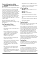
Electrical Connection Safety • THE APPLIANCE MUST BE n WARNING: EARTHED. An appliance for use on LPG must not be installed in a room or internal space below ground level, e.g. in a basement. If You Smell Gas The cooker is preset for a single-phase earthed electrical connection. It is essential to install a multi-pole circuit breaker that completely disconnects the appliance from the mains, with a minimum contact break distance of 3 mm.
WARNING: Unattended cooking on a n hob with fat or oil can be dangerous and cookerhood that vents outside. If you have several hotplates/burners on, or use the cooker for a long time, open a window or turn on an extractor fan may result in fire. n Maintenance • It is recommended that this appliance is serviced annually. NEVER try to extinguish a fire with water, but switch off the appliance and then cover the flame e.g. with a lid or a fire blanket. • NEVER leave a chip pan unattended.
• Fig. 1.1 If flammable materials are stored in the drawer, oven(s) or grill(s) it may explode and result in fire or property damage. Oven Care ArtNo.324-0001 Steam burst Fig. 1.2 Front bracket Rear stop FRONT Fig. 1.3 Fig. 1.4 ArtNo.312-0003 Moving pans 4 • When the oven is not in use and before attempting to clean the cooker always be certain that the control knobs are in the OFF position. • Use oven gloves to protect your hand from potential burns.
• DO NOT use a timed oven that is already warm. • Use dry oven gloves when applicable – using damp gloves might result in steam burns when you touch a hot surface. WARNING: Should a crack appear n in the surface, disconnect the cooker immediately from the supply and arrange for its repair. Always LIFT pans off the heating zone. Sliding pans may cause marks and scratches (Fig. 1.4). Always turn the control to the ‘OFF’ position before removing a pan.
• Avoid heating an empty pan. Doing so may damage both the hob and pan. • NEVER use paint solvents, washing soda, caustic cleaners, biological powders, bleach, chlorine based bleach cleaners, coarse abrasives or salt. • DO NOT mix different cleaning products – they may react together with hazardous results. • All parts of the cooker can be cleaned with hot soapy water. • Take care that no water seeps into the appliance.
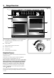
2. Range Overview Fig. 2.1 A B C E D F The 110 dual fuel cooker (Fig. 2.1) has the following features: A. 4 hotplate burners, a Wok Burner and a Ceramic Multizone hotplate B. Control Panel C. Glide-out Grill™ with 4 position Trivet D. Multifunction Oven E. Steam cavity F. Bread Proving/Storage Drawer Fig. 2.2 Hotplate Burners The labels by each of the control knobs indicates which area that knob controls.
If and when you let go of the control knob or the burner goes out, then the FSD has not been bypassed. Turn the control knob to the OFF position and wait for one minute before you try again, this time making sure to hold in the control knob for slightly longer. Fig. 2.3 Adjust the flame height to suit by turning the knob counterclockwise (Fig. 2.3). On this cooker the low position is beyond high, NOT between high and off.
The Ceramic Hotplate Fig. 2.11 The hotplate area on the left-hand side is dual purpose. It can be used either as a ceramic hob to heat a pan in the usual way (Fig. 2.11) or it can be used to heat the supplied griddle. The rear area, marked with a ring, is for cooking with a pan. There are two elements that allow either the whole of the area to be heated or just the rear half. To heat the whole area, turn the hotplate control clockwise (Fig. 2.12).
The Griddle Fig. 2.16 The griddle (Fig. 2.17) is designed to fit securely on the locating pins over the ceramic heating area (Fig. 2.18). DO NOT try to use it over one of the gas burners. It will not be securely held and you may damage the non-stick finish. To heat the whole area, turn the hotplate control clockwise (Fig. 2.19). ArtNo.312-0006 Correct pan sizes The neon indicator light above the control knob will come on when a hob control is turned on and stay lit while the surface cools. Fig. 2.
Bread Proving Drawer Fig. 2.22 The Bread Proving Drawer is found on the right at the base of the cooker (Fig. 2.22). Within the Bread Proving Drawer there are slots in the base to allow warmed air to flow through into the drawer from the element underneath. The Bread Proving Drawer temperature is ideal for proving all sorts of yeast dough from sweet to savoury, gluten free to sourdough, dough made from fresh yeast and dried, bread mixes and recipes from the Rangemaster Good Housekeeping Cookery book.
Cleaning Fig. 2.24 Clean the inside of the drawer with hot soapy water and a soft cloth, rinse and dry. The Bread Proving Drawer is ideal for storing baking trays and other cooking utensils. It can get warm, so do not store anything in it that may melt or catch fire. n Never store flammable materials in the drawer. This includes paper, plastic and cloth items, such as cookbooks, plastic ware and towels, as well as flammable liquids.
3. Using the Glide-out Grill™ DocAUS.020-0004 - Overview - 110DF - Elan Fig. 3.2 Fig. 3.1 Nearest to the element Middle High Middle Low Furthest from the element Four grill height positions refer to Fig. 3.5 Fig. 3.4 Fig. 3.3 To switch on both elements To switch on the right half element Fig. 3.5 Four grill height positions Nearest to the element Middle High 180o Cooking suggestions Furthest from the element 180o Middle Low 180o 180o 1. Nearest to the element – Toast, streaky bacon. 2.
4. The Multifunction Oven The clock must be set to the time of day before the oven will work. See the section on ‘The Clock’ for instructions on setting the time of day. Symbol Function Use Fan References to ‘left-hand’ and ‘right-hand’ ovens apply as viewed from the front of the appliance. A full cooking function, even heat throughout, great for baking Duo The left-hand oven is a multifunction oven, while the righthand is a steam cavity. Gentle form of heating using base heat and fan.
ECO Mode Fig. 4.2 This setting saves energy, cooking in fanned mode, for foods requiring a cooking time of 45 minutes or less. No preheating . Note: The oven door must remain closed during ECO mode. Failure to do so will result in the oven continuing to cook after the pre-set 45 minutes. The following foods are recommended for the ECO setting: • Ready prepared meals - meals should have the maximum duration of 45 minutes from chilled, and must not be frozen.
Accessories Fig. 4.3 Front bracket Glide-out Oven Shelves Rear stop The left-hand oven is supplied with 2 glide-out oven shelves. To fit the glide-out shelf, hook the front of the shelf onto the runners as shown (Fig. 4.3). The rear of the shelf should rest on the runners, in front of the rear stop (Fig. 4.3). The glide-out shelf and runners can be easily removed or repositioned. To remove the glide-out shelf Raise the rear of the shelf, so that it clears the rear stops.
The Handyrack (Optional extra) Fig. 4.11 The Handyrack (Fig. 4.11) fits to the left-hand oven door only. Food cooking on it is easy to attend to, because it is accessible when the door is open. The maximum weight that can be held by the Handyrack is 5.5 kg (12 lb). It should only be used with the supplied roasting tin, which is designed to fit the Handyrack. Any other vessel could be unstable. ArtNo.320-0014 Handyrack on LH door Fig. 4.12 It can be fitted at two different heights.
4. Once the specified time has elapsed an alarm will sound. It will stop automatically after 10 seconds. 5. To cancel the minute minder, and enter a new time, tap the clock button whilst the [ ] symbol is active. Fig. 4.17 To stop the multifunction oven after a specific time 1. Set the cooking function and temperature (see “Operating the Multifunction Oven” on page 14). 2. Touch and hold the ‘timer’ button until the cook period symbol [ ] is displayed (Fig. 4.17).
Cooking Tips General oven tips Tips on cooking with the timer The wire shelves should always be pushed firmly to the back of the oven. If you want to cook more than one dish, choose dishes that require approximately the same cooking time. However, dishes can be ‘slowed down’ slightly by using small containers and covering them with aluminium foil, or ‘speeded up’ slightly by cooking smaller quantities or placing them in larger containers.
Cooking Table The oven control settings and cooking times given in the table below are intended to be used as a guide only. Individual tastes may require the temperature to be altered to provide a preferred result. Food is cooked at lower temperature in a fan oven than in a conventional oven. When using recipes, reduce the fan oven temperature by 10 °C and the cooking time by 5-10 minutes. The temperature in the fan oven does not vary with height in the oven so you can use any shelf.
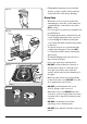
5. The Steam Cavity Fig. 5.1 A G B C D E Key A Water Tank B Door Seal C 1 x Rack D 1 x Pan E 1 x Perforated Pan F Door G Sponge F The Steam Cavity (right-hand) Fig. 5.2 1 2 3 The steam cavity is shown in Fig. 5.1. 4 Fig. 5.2 shows the touch sensitive control panel for the steam cavity. Water Level 5 6 7 To fill the water tank or check the water level lift and pull the water tank from the oven cavity (Fig. 5.1).
Operating the Steam Cavity Fig. 5.4 Note: The steam cavity may start a pump out cycle (Fig. 5.12) when first turned on. This is normal and it should be allowed to complete. The cycle will take approximately 2 minutes. 1. Touch and hold the standby button to switch the steam cavity on (Fig. 5.4). The display will show the maximum tempertaure; 100 ºC, a 15 minute cook time and the steam icon will flash (Fig. 5.5). 2. To adjust the temperature, touch and hold the temperature button (Fig. 5.
Steam Cavity Functions Fig. 5.13 The steam cavity has three main functions: steam grill descale Switch the oven on and tap the [ + ] or [ - ] buttons to scroll through these functions. Program Modes The steam cavity has pre-programmed modes for different food types. To access these modes touch and hold the standby button to switch the steam cavity on. Touch and hold the program button (Fig. 5.13). [ A1 ] will show in the display. Scroll through the programs using the [ + ] or [ - ] buttons.
The Clock / Timer Fig. 5.14 The clock above the multi-function oven must be set to the time of day before the multi-function oven or steam cavity will work. See "Setting the clock" on page 17. Note: The steam cavity control does not show the time of day. This is automatically set from the multi-function oven control. The display will remain blank until the steam cavity is turned on. Fig. 5.15 To stop the steam cavity at a specific time of day 1.
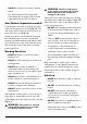
6. Cleaning Your Cooker Essential Information n Never use paint solvents, washing soda, caustic cleaners, biological powders, bleach, chlorine based bleach cleaners, coarse abrasives or salt. n Do not mix different cleaning products – they may react together with hazardous results. C B E D All parts of the cooker can be cleaned with hot soapy water – but take care that no surplus water seeps into the appliance. ArtNo.
Ceramic Hotplate Fig. 6.5 Daily Care First of all, make sure that the heat indicator light is off and that the cooking surface is cool. Apply a small dab of ceramic cleaning cream in the centre of the area to be cleaned. Dampen a clean paper towel and work the cream onto the cooking surface. As a final step, wipe the cooking surface with a clean, dry paper towel.
Grills Fig. 6.6 The grill pan and trivet should be washed in hot soapy water. Alternatively, the grill pan can be washed in a dishwasher. After grilling meats or any foods that soil, leave to soak for a few minutes immediately after use. Stubborn particles may be removed from the trivet using a nylon brush. n Before you remove any of the grill parts for cleaning, make sure that they are cool, or use oven gloves. n DO NOT use any abrasive substances. Fig. 6.
Control Panel and Doors Fig. 6.10 Avoid using any abrasive cleaners, including cream cleaners. For best results, use a liquid detergent. The same cleaner can also be used on the doors. Alternatively, use a soft cloth wrung out in clean hot soapy water. You can use the same method for cleaning the control panel and knobs. After cleaning, polish with a dry cloth. Glass Fronted Door Panels ArtNo.
Steam Cavity n Fig. 6.12 Before cleaning your oven or performing maintenance, please switch off the power supply. In order to prolong the service life of steam cavity, please note the following points: The enameled or stainless steel parts should be washed with lukewarm water without using any abrasive powders or corrosive substances which could scratch, stain and damage the oven. After cleaning, it is advisable to rinse thoroughly and dry.
Cleaning Table Cleaners listed (Table 6.1) are available from supermarkets or electrical retailers as stated. For enamelled surfaces use a cleaner that is approved for use on vitreous enamel. Regular cleaning is recommended. For easier cleaning, wipe up any spillages immediately. Hotplate Part Finish Recommended Cleaning Method Hob top (including burner heads and caps) Enamel, stainless steel, aluminium Hot soapy water, soft cloth. Any stubborn stains remove gently with a nylon scourer.
7. Troubleshooting Hotplate/Cooktop ignition or hotplate burners faulty Food is cooking too slowly, too quickly, or burning Is the power on? Is the clock illuminated? Cooking times may differ from your previous oven. If not, there maybe something wrong with the power supply. Check that you are using the recommended temperatures and shelf positions – see the oven cooking guide. The oven control settings and cooking times are intended to be used only as a guide.
Multifunction oven light is not working Fig. 7.1 The bulb has probably burnt out. You can buy a replacement bulb (which is not covered under the warranty) from a good electrical shop. Ask for a 40W - 230V halogen lamp (G9) (Fig. 7.3). Fig. 7.2 Before removing the existing bulb, turn off the power supply and make sure that the oven and bulb have cooled. Open the oven door and remove the oven shelves. Remove the bulb cover by turning it a quarter turn, counterclockwise. It may be very stiff (Fig. 7.4).
Error Codes Multifunction oven Error Code Error description Comment HE 1 Oven sensor NTC short circuit or open circuit HE 2 Meat probe short circuit HE 3 Communication problem between UI and power PCB Not applicable Steam cavity Error Code Error description Comment HE 1 Oven sensor NTC short circuit or open circuit HE 2 Water boiler sensor open circuit or short circuit HE 3 Water level sensor switch cut - Hi or Low Sensor HE 4 After press button 8, door switch short circuit HE 5 Water
INSTALLATION Check the appliance is electrically safe when you have finished. 8. Service and Spares Firstly, please complete the appliance details below and keep them safe for future reference – this information will enable us to accurately identify the particular appliance and help us to help you. Filling this in now will save time and inconvenience if you later have a problem with the appliance. It may also be of benefit to keep your purchase receipt with this leaflet.
INSTALLATION Check the appliance is gas sound when you have finished. 9. Installation Safety Requirements and Regulations Provision of Ventilation This appliance is not connected to a combustion products evacuation device. Particular attention shall be given to the relevant requirements regarding ventilation. You must be aware of the following safety requirements & regulations.
INSTALLATION Check the appliance is gas sound when you have finished. 3 pan supports 2 x set of Telescopic runners Wok cradle (Supplied) ArtNo.000-0009 Wok ring, cast ArtNo.110-0002 110 pan supports Griddle plate (Supplied) Teppanyaki (Optional) Griddle Plate (Optional) You will need the following equipment to complete the cooker installation satisfactorily: • * Restraining chain and hook: If the cooker is to be supplied with gas through a flexible hose, a restraining chain and hook MUST be fitted.
INSTALLATION Check the appliance is gas sound when you have finished. Positioning the Cooker Fig. 9.1 The diagram (Fig. 9.1) shows the minimum recommended distance from the cooker to nearby surfaces as given in AS/NZS 5601. Where the appliance is installed next to cabinetry, the cabinet material must be capable of withstanding 70°C. If this appliance is installed near vinyl wrapped surfaces, use an installation kit available from the vinyl-wrap supplier.
INSTALLATION Check the appliance is gas sound when you have finished. be possible to move the cooker in and out for cleaning and servicing. Fig. 9.3 Moving the Cooker n On no account try and move the cooker while it is plugged into the electricity supply. n The cooker is very heavy, so take extra care. We recommend that two people manoeuvre the cooker. Make sure that the floor covering is firmly fixed, or removed, to prevent it being disturbed when moving the cooker around. Fig. 9.
INSTALLATION Check the appliance is gas sound when you have finished. Fitting a Stability Bracket Fig. 9.7 When fitting a stability bracket (Fig. 9.7) please refer to the instructions supplied with the bracket for further details on fitting. When fitting a stability bracket (Fig. 9.8 and Fig. 9.9) adjust the bracket to give the smallest practicable clearance between the bracket and the engagement slot in the rear of the cooker.
INSTALLATION Check the appliance is gas sound when you have finished. Gas Connection Fig. 9.11 This must be in accordance with the relevant standards. 675 Gas inlet 315 The gas supply needs to terminate with a down-facing threaded fitting ½” connection. The inlet connector is located just below the hotplate level at the rear of the cooker. A Because the height of the cooker can be adjusted and each connection is different, it is difficult to give precise dimensions.
INSTALLATION Check the appliance is gas sound when you have finished. Electrical Connection Current Operated Earth Leakage Breakers This appliance must be installed by a qualified electrician to comply with with current AS/NZS 3000 Wiring Rules and regulations in force. The combined use of your cooker and other domestic appliances may cause nuisance tripping, so we recommend that the cooker is protected on an individual RCD (Residual Current Device) or RCBO (Residual Current Breaker with Overload).
INSTALLATION Check the appliance is gas sound when you have finished. Connection in New Zealand Fig. 9.14 Type of cord in accordance with IEC 60227 with a minimum rating of 90°C. Cord size recommended for this application is 3 x 10 mm², three-core cable (Power cables may be sized to take into account the coincidence factor AS/NZS 60335.2.6:2014). Rating of the plug is 32 Amp, in accordance with AS/NZS 3112.
INSTALLATION Check the appliance is gas sound when you have finished. Final Fittings and Checks Fig. 9.19 Hob Check Check each cooking zone in turn. Be sure to use pans of the correct size and material. Grill Check Turn on the grill control and check that the grill heats up. Oven Check Set the clock as described earlier, and then turn on the ovens. Check the oven fans start to turn and that the ovens heat up. ArtNo.
WARNING – SERVICING TO BE CARRIED OUT ONLY BY AN AUTHORISED PERSON Disconnect from electricity and gas before servicing. Check appliance is safe when you have finished. 10. Conversion to LP Gas Conversion from Natural Gas (1.0 kPa) to LPG X Propane (2.54 kPa) n A suitably competent person must perform the conversion. After conversion the installation must comply with the relevant regulations and also the local electricity supply company requirements.
WARNING – SERVICING TO BE CARRIED OUT ONLY BY AN AUTHORISED PERSON Disconnect from electricity and gas before servicing. Check appliance is safe when you have finished. Set the Governor Fig. 10.3 Unscrew the governor’s brass top. In the base of the brass top is a plastic snap-in converter device (Fig. 10.3). To convert the governor, snap the device out of the top and refit it the other way round. The snap-in converter device is marked to show the gas for which it is set (Fig. 10.4). ArtNo.
WARNING – SERVICING TO BE CARRIED OUT ONLY BY AN AUTHORISED PERSON Disconnect from electricity before servicing. Check appliance is safe when you have finished. 11. Servicing Fig. 11.1 n BEFORE SERVICING ANY GAS CARRYING COMPONENTS TURN OFF THE GAS SUPPLY n Check the appliance is gas sound after completion of service. When checking for gas leaks do not use washing up liquid – this can corrode. Use a product specifically manufactured for leak detection.
WARNING – SERVICING TO BE CARRIED OUT ONLY BY AN AUTHORISED PERSON Disconnect from electricity before servicing. Check appliance is safe when you have finished. 2.6 To Change a Hotplate Burner Thermocouple reconnected. Take care not to damage the ignition electrodes of the burners. n It is important that the rear earthing leads are replaced when the fixing screws are refitted as they from part of the cooker earthing. Remove the hotplate (see 2.1). Unplug the FSD lead from the rear of the tap.
WARNING – SERVICING TO BE CARRIED OUT ONLY BY AN AUTHORISED PERSON Disconnect from electricity before servicing. Check appliance is safe when you have finished. 4 Grill Fig. 11.2 4.1 To Replace the Grill Controller n DISCONNECT FROM THE ELECTRICITY SUPPLY. Remove the control panel and hotplate (see 1.1 & 2.1). Disconnect the wiring from controller. Remove the 2 screws holding the controller to the mounting panel. Fit the new controller and reassemble in the reverse order. Check for correct operation.
WARNING – SERVICING TO BE CARRIED OUT ONLY BY AN AUTHORISED PERSON Disconnect from electricity before servicing. Check appliance is safe when you have finished. 5.3 To Change the Fan in the Left-hand Oven n Fig. 11.3 DISCONNECT FROM THE ELECTRICITY SUPPLY. Pull the cooker forward to gain access to the rear. Remove the screws securing the electric cover to the back sheet and remove the cover. Disconnect the 3 terminals connected to the fan, noting their position.
WARNING – SERVICING TO BE CARRIED OUT ONLY BY AN AUTHORISED PERSON Disconnect from electricity before servicing. Check appliance is safe when you have finished. Fig. 11.6 Top Element Fig. 11.7 Open the left-hand oven door and undo the fixings that secure the heat shield. Remove the top element bracket fixings and withdraw element. Replace the element and reassemble parts in reverse order. Check the oven operation. 2 1 ArtNo.320-0001 Door hinges Fig. 11.8 ArtNo.320-0001 Door hinges 6 Doors 6.
WARNING – SERVICING TO BE CARRIED OUT ONLY BY AN AUTHORISED PERSON Disconnect from electricity before servicing. Check appliance is safe when you have finished. 6.6 To Adjust an Oven Door Catch Keep Fig. 11.12 Fig. 11.11 Open the oven door, slacken off the locknut at the base of the keep, and screw in or out as required until the required fit is obtained. Retighten the locking nut (Fig. 11.12). ArtNo.320-0004 Oven door keep 6.7 To Change an Oven Door Seal Open the oven door.
12. Circuit Diagram b b br br br br br X27 b r X26 X26 br bk br bk b r X10 g b w X11 b y X09 b b v X22 bk 1.1kW X34 br v br v br v br v r v X30 X31 v f b b b d e c b bk a br v 1 Steam Oven b b bk b b r y r X28 bk r v X26 br X34 X02 bk r b 1.
Power PCB X27 br w y g r bk bk r br or M M X59 M X58 M X57 X16 X31 X54 X53 X08 X10 X11 X09 M br X56 A X55 b Rotisserie(Not Used) b N b w w r r w br ACL A5 A10 ACN bk Connector P1 A11 A12 Connector P2 Con 15 POWER PCB BOARD Con 3 bk X51 A1 A6 PE Con 6 w w A2 A7 b g/y X52 A3 A8 Con 1 Con 4 w w b b X46 X45 Con 10 Con 8 y y y X47 Con 5 Con 7 Con 2 Protective Earth A4 A9 bk bk bk bk X50 X49 y X48 11 Function UI (X43) Steam Ov
13. Technical Data THE COOKER IS CATEGORY: CatII2H3+. It is supplied set for group H natural gas. A conversion kit from NG to LP is available for the cooker. INSTALLER: Please leave these instructions with the user. DATA BADGE LOCATION: Cooker back, serial number repeater badge below oven door opening. COUNTRY OF DESTINATION: Australia. Pressures Gas (Rp ½ at rear right-hand side) Electric Supply Pressure at the inlet to appliance regulator Natural Gas 1.13 kPa Propane 2.
Clarence Street, Royal Leamington Spa, Warwickshire, CV31 2AD, England. www.falconworld.