USER GUIDE & INSTALLATION INSTRUCTIONS Nexus 110 Induction / Steam Australia U111144 - 04
Contents 1. 2. Before You Start... 1 Cleaning Your Cooker 29 Personal Safety 1 Hob 29 Electrical Connection Safety 2 Glide-out Grill™ 30 Peculiar Smells 3 Control Panel and Doors 31 Ventilation 3 Multifunction Oven 31 Maintenance 3 Steam Cavity 32 Induction care 4 Cleaning Table 33 Grill/Glide-out Grill™ Care 7 Cooling Fan 7 Cooker Care 7 Cleaning Cooker Overview 7. Troubleshooting 34 8.
ii
1. Before You Start... Your cooker should give you many years of trouble-free cooking if installed and operated correctly. It is important that you read this section before you start. Personal Safety • DO NOT operate this appliance before reading the instruction booklet. • DO NOT place articles on or against this appliance. • DO NOT operate with panels, covers or guards removed from this appliance. • The cooker should not be placed on a base.
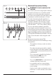
Electrical Connection Safety Fig. 1.1 THE APPLIANCE MUST BE n WARNING: EARTHED. The cooker is preset for a single-phase earthed electrical connection. It is essential to install a multi-pole circuit breaker that completely disconnects the appliance from the mains, with a minimum contact break distance of 3 mm. ArtNo.132-0001 - 1 phase 240Vac 50Hz 1-phase 230 VAC 50 Hz The total electrical load of the appliance is approximately 12.15 kW.
• The appliance must be installed in accordance with the regulations in force and only in a well ventilated space. Maintenance • It is recommended that this appliance is serviced annually. • Failure to install the appliance correctly could invalidate any warranty or liability claims and lead to prosecution. • • DO NOT install the appliance on a platform. WARNING: Before replacing the bulb, turn off the power supply and make sure that the oven is cool.
n NEVER try to extinguish a fire with water, but switch off the appliance and then cover the flame e.g. with a lid or a fire blanket. • NEVER leave a chip pan unattended. Always heat fat slowly, and watch as it heats. Deep fry pans should be only one third full of fat. • WARNING: Danger of fire: do not store Induction care • of this hob comply with the applicable European standards on electromagnetic interference.
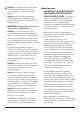
• Take care NOT to scratch the surface when placing cookware on the glass panel. • Only certain types of glass, glass-ceramic, earthenware or other glazed containers are suitable for hotplate cooking; others may break because of the sudden change in temperature. NEVER cook directly on the hob surface (Fig. 1.4). Fig. 1.3 Fig. 1.4 Fig. 1.5 • DO NOT leave the hob zones switched on ArtNo.312-0001 Not cooking surface unless being used for cooking. • DO NOT stand or rest heavy objects on the hob.
Fig. 1.8 • We recommend that you avoid wiping any surface unit areas until they have cooled and the indicator light has gone off. Sugar spills are the exception to this (see ‘Cleaning your Cooker’). After cleaning, use a dry cloth or paper towel to remove any cleaning cream residue. • The ceramic surface should be washed after use in order to prevent it from becoming scratched or dirty. However, you should clean the hob with caution as some cleaners can produce noxious fumes if applied to a hot surface.
• • • Make sure the shelves are pushed firmly to the back of the oven. DO NOT close the door against the oven shelves. DO NOT use aluminium foil to cover shelves, linings or the oven roof. When the oven is on, DO NOT leave the oven door open for longer than necessary, otherwise the control knobs may become very hot. • DO NOT use the timed oven if the adjoining oven is already warm. • DO NOT place warm food in the oven to be timed. • DO NOT use a timed oven that is already warm.
Cleaning • Isolate the electricity supply before carrying out any thorough cleaning. Allow the cooker to cool. • In the interests of hygiene and safety, the cooker should be kept clean at all times as a build up in fats and other food stuff could result in a fire. • Clean only the parts listed in this guide. • Clean with caution. If a wet sponge or cloth is used to wipe spills on a hot surface, be careful to avoid steam burns. Some cleaners can produce noxious fumes if applied to a hot surface.
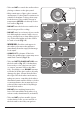
2. Cooker Overview Fig. 2.1 A M 0 0 L1 L2 9 0 L1 L2 L3 9 1 0 L1 L2 L3 9 0 L1 L2 L3 1 1 9 L1 L2 L3 1 9 L3 1 B C E D F Your 110 induction cooker (Fig. 2.1) has the following features: A. 5 induction cooking zones B. Control panel C. Glide-out grill with 4 position trivet D. Multifunction oven E. Steam cavity F. Bread Proving/Storage Drawer Fig. 2.2 The Hob Fig. 2.3 Use only pans that are suitable for induction hobs.
The very best pans have bases that are very slightly curved up when cold (Fig. 2.3). If you hold a ruler across the bottom you will see a small gap in the middle. When they heat up the metal expands and lies flat on the cooking surface. Fig. 2.4 Max: 1.85 kW Boost: 2.5 kW Max: 1.85 kW Boost: 3.2 kW Max: 1.85 kW Boost: 2.5 kW Make sure that the base of the pan is clean and dry to prevent any residue burning onto the hob panel. This also helps prevent scratches and deposits.
Residual Heat Indicator, H Fig. 2.6 After use, a cooking zone will remain hot for a while as heat dissipates. When a cooking zone is switched off the residual heat indicator symbol [H ], will appear in the display. This shows that the cooking zone temperature is above 60 °C and may still cause burns. Once the temperature has dropped to below 60 °C the [H ] will go out. Child Lock, n IMPORTANT: The child lock can only be activated when all the cooking zones are switched off. Fig. 2.
Power Boost Setting, P A & B linked Fig. 2.8 All of the induction cooking zones have Power Boost available, activated by turning the control knob clockwise until [P ] is shown on the hob control display. D A C B Power Boost allows additional power to be made available for each of the cooking zones. This is useful to bring a large pan of water to the boil quickly. E The Power Boost function operates for a maximum of 10 minutes on each zone, after which the power is automatically reduced to setting 9.
n DO NOT turn the two left-hand knobs individually to heat the griddle plate. This can cause excessive temperatures and damage the coating on the griddle plate. Fig. 2.14 Overheat Function This function identifies when the temperature of the pan rises rapidly and works to maintain a safe level of pan temperature. It should not interfere with normal cooking. Cookware with bases that become distorted (Fig. 2.2) when heated may interfere with the operation of the Overheat Function.
Bread Proving Drawer Fig. 2.15 The Bread Proving Drawer is found on the right at the base of the cooker (Fig. 2.15). Within the Bread Proving Drawer there are slots in the base to allow warmed air to flow through into the drawer from the element underneath. The Bread Proving Drawer temperature is ideal for proving all sorts of yeast dough from sweet to savoury, gluten free to sourdough, dough made from fresh yeast and dried, bread mixes and recipes from the Rangemaster Good Housekeeping Cookery book.
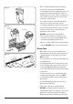
Telescopic shelf - Left-hand (Main) Oven Fig. 2.17 As well as standard shelves, the left-hand oven is supplied with a set of runners for a glide-out oven shelf. Front bracket Rear stop To fit the glide-out shelf, hook the front of the shelf onto the runners as shown (Fig. 2.17). The rear of the shelf should rest on the runners, in front of the rear stop (Fig. 2.17). The glide-out shelf and runners can be easily removed or repositioned.
3. Using the Glide-out Grill™ DocAUS.020-0004 - Overview - 110DF - Elan Fig. 3.2 Fig. 3.1 Nearest to the element Middle High Middle Low Furthest from the element Four grill height positions refer to Fig. 3.5 Fig. 3.4 Fig. 3.3 To switch on both elements To switch on the right half element Four grill height positions Nearest to the element Fig. 3.5 Middle High 180o Cooking suggestions Furthest from the element 180o Middle Low 180o 180o 1. Nearest to the element – Toast, streaky bacon. 2.
4. The Multifunction Oven The clock must be set to the time of day before the oven will work. See the section on ‘The Clock’ for instructions on setting the time of day. Symbol Function Use Fan References to ‘left-hand’ and ‘right-hand’ ovens apply as viewed from the front of the appliance. A full cooking function, even heat throughout, great for baking Duo The left-hand oven is a multifunction oven, while the righthand is a steam cavity. Gentle form of heating using base heat and fan.
ECO Mode Fig. 4.2 This setting saves energy, cooking in fanned mode, for foods requiring a cooking time of 45 minutes or less. No preheating . Note: The oven door must remain closed during ECO mode. Failure to do so will result in the oven continuing to cook after the pre-set 45 minutes. The following foods are recommended for the ECO setting: • Ready prepared meals - meals should have the maximum duration of 45 minutes from chilled, and must not be frozen.
Accessories Fig. 4.3 Front bracket Glide-out Oven Shelves Rear stop The left-hand oven is supplied with 2 glide-out oven shelves. To fit the glide-out shelf, hook the front of the shelf onto the runners as shown (Fig. 4.3). The rear of the shelf should rest on the runners, in front of the rear stop (Fig. 4.3). The glide-out shelf and runners can be easily removed or repositioned. To remove the glide-out shelf Raise the rear of the shelf, so that it clears the rear stops.
The Handyrack (Optional extra) Fig. 4.11 The Handyrack (Fig. 4.11) fits to the left-hand oven door only. Food cooking on it is easy to attend to, because it is accessible when the door is open. The maximum weight that can be held by the Handyrack is 5.5 kg (12 lb). It should only be used with the supplied roasting tin, which is designed to fit the Handyrack. Any other vessel could be unstable. ArtNo.320-0014 Handyrack on LH door Fig. 4.12 It can be fitted at two different heights.
4. Once the specified time has elapsed an alarm will sound. It will stop automatically after 10 seconds. 5. To cancel the minute minder, and enter a new time, tap the clock button whilst the [ ] symbol is active. Fig. 4.17 To stop the multifunction oven after a specific time 1. Set the cooking function and temperature (see “Operating the Multifunction Oven” on page 17). 2. Touch and hold the ‘timer’ button until the cook period symbol [ ] is displayed (Fig. 4.17).
Cooking Tips General oven tips Tips on cooking with the timer The wire shelves should always be pushed firmly to the back of the oven. If you want to cook more than one dish, choose dishes that require approximately the same cooking time. However, dishes can be ‘slowed down’ slightly by using small containers and covering them with aluminium foil, or ‘speeded up’ slightly by cooking smaller quantities or placing them in larger containers.
Cooking Table The oven control settings and cooking times given in the table below are intended to be used as a guide only. Individual tastes may require the temperature to be altered to provide a preferred result. Food is cooked at lower temperature in a fan oven than in a conventional oven. When using recipes, reduce the fan oven temperature by 10 °C and the cooking time by 5-10 minutes. The temperature in the fan oven does not vary with height in the oven so you can use any shelf.
5. The Steam Cavity Fig. 5.1 A G B C D E Key A Water Tank B Door Seal C 1 x Rack D 1 x Pan E 1 x Perforated Pan F Door G Sponge F The Steam Cavity (right-hand) Fig. 5.2 1 2 3 The steam cavity is shown in Fig. 5.1. 4 Fig. 5.2 shows the touch sensitive control panel for the steam cavity. Water Level 5 6 7 To fill the water tank or check the water level lift and pull the water tank from the oven cavity (Fig. 5.1).
Operating the Steam Cavity Fig. 5.4 Note: The steam cavity may start a pump out cycle (Fig. 5.12) when first turned on. This is normal and it should be allowed to complete. The cycle will take approximately 2 minutes. 1. Touch and hold the standby button to switch the steam cavity on (Fig. 5.4). The display will show the maximum tempertaure; 100 ºC, a 15 minute cook time and the steam icon will flash (Fig. 5.5). 2. To adjust the temperature, touch and hold the temperature button (Fig. 5.
Steam Cavity Functions Fig. 5.13 The steam cavity has three main functions: steam grill descale Fig. 5.14 Switch the oven on and tap the [ + ] or [ - ] buttons to scroll through these functions. Using the Steam Grill Fig. 5.15 1. Touch and hold the standby button to switch the steam cavity on (Fig. 5.13) then use the [ + ] or [ - ] buttons to scroll through to the grill function (Fig. 5.14). 2. The default temperature is 180 ºC.
Program Modes The steam cavity has pre-programmed modes for different food types. To access these modes touch and hold the standby button to switch the steam cavity on. Touch and hold the program button (Fig. 5.13). [ A1 ] will show in the display. Scroll through the programs using the [ + ] or [ - ] buttons. Touch and hold the program button again to access the next set of progams for fish. [ b1 ] will be displayed. Touch and hold the program button a third time to access the programs for meat.
The Clock / Timer Fig. 5.18 The clock above the multi-function oven must be set to the time of day before the multi-function oven or steam cavity will work. See "Setting the clock" on page 20. Note: The steam cavity control does not show the time of day. This is automatically set from the multi-function oven control. The display will remain blank until the steam cavity is turned on. Fig. 5.19 To stop the steam cavity at a specific time of day Fig. 5.20 1.
6. Cleaning Your Cooker Isolate the electricity supply before carrying out any major cleaning. Allow the cooker to cool. Fig. 6.1 n NEVER use paint solvents, washing soda, caustic cleaners, biological powders, bleach, chlorine based bleach cleaners, coarse abrasives or salt. n DO NOT mix different cleaning products – they may react together with hazardous results. All parts of the cooker can be cleaned with hot soapy water. Take care that no surplus water seeps into the appliance.
Glide-out Grill™ Fig. 6.2 The grill pan and trivet should be washed in hot soapy water. Alternatively, the grill pan can be washed in a dishwasher. After grilling meats or any foods that soil, leave to soak for a few minutes immediately after use. Stubborn particles may be removed from the trivet using a nylon brush. n Before you remove any of the grill parts for cleaning, make sure that they are cool, or use oven gloves. n DO NOT use any abrasive substances. Removing the Glide-out Grill Pan Fig. 6.
Control Panel and Doors Fig. 6.6 Avoid using any abrasive cleaners, including cream cleaners. For best results, use a liquid detergent. The same cleaner can also be used on the doors. Alternatively, use a soft cloth wrung out in clean hot soapy water. You can use the same method for cleaning the control panel and knobs. After cleaning, polish with a dry cloth. Glass Fronted Door Panels ArtNo.
Steam Cavity n Fig. 6.8 Before cleaning your oven or performing maintenance, please switch off the power supply. In order to prolong the service life of steam cavity, please note the following points: The enameled or stainless steel parts should be washed with lukewarm water without using any abrasive powders or corrosive substances which could scratch, stain and damage the oven. After cleaning, it is advisable to rinse thoroughly and dry.
Cleaning Table Cleaners listed (Table 6.1) are available from supermarkets or electrical retailers as stated. For enamelled surfaces use a cleaner that is approved for use on vitreous enamel. Regular cleaning is recommended. For easier cleaning, wipe up any spillages immediately. Hotplate Part Finish Recommended Cleaning Method Hob top (including burner heads and caps) Enamel, stainless steel, aluminium Hot soapy water, soft cloth. Any stubborn stains remove gently with a nylon scourer.
7. n Troubleshooting DocNo.050-0001 - Troubleshooting - Induction GENERIC Interference with and repairs to the hob MUST NOT be carried out by unqualified persons. Do not try to repair the hob as this may result in injury and damage to the hob. Please arrange for repair by a suitably competent person. The cooling fan The induction hob incorporates a cooling fan. This cooling fan is active when either the grill or the oven(s) are on.
The oven is not cooking evenly Fig. 7.1 Do not use a baking tray with dimensions larger than those specified in the section on ‘General Oven Tips’. If you are cooking a large item, be prepared to turn it round during cooking. If two shelves are used, check that space has been left for the heat to circulate. When a baking tray is put into the oven, make sure that it is placed centrally on the shelf.
The left-hand oven door is misaligned Fig. 7.3 The bottom hinge of the left-hand oven door can be adjusted to alter its angle (Fig. 7.3). Loosen the bottom hinge fixing screws and use the notch and a flat bladed screwdriver to move the position of the hinge to set the hinge position (Fig. 7.4). ArtNo.320-0006 Oven door hinge adjustment 1 Retighten the hinge screws. Steam cavity light is not working Effect of hinge adjustment – exagerrated for clarity The bulb has probably burnt out.
INSTALLATION Check the appliance is electrically safe and gas sound when you have finished. 8. Installation Dear Installer Location of Cooker Before you start your installation, please complete the details below, so that, if your customer has a problem relating to your installation, they will be able to contact you easily. The cooker may be installed in a kitchen/kitchen diner but NOT in a room containing a bath or shower.
INSTALLATION Check the appliance is electrically safe and gas sound when you have finished. Positioning the Cooker Fig. 8.1 Fig. 8.1 and Fig. 8.2 shows the minimum recommended distance from the cooker to nearby surfaces. 75 mm min The cooker should not be placed on a base. 650 mm min 75 mm min Fig. 8.1 and Fig. 8.2 Cookers installed into recess: The cooker must have side clearance ABOVE hob level of 75mm up to a height of 410mm.
INSTALLATION Check the appliance is electrically safe and gas sound when you have finished. Lowering the Two Rear Rollers Fig. 8.5 To adjust the height of the rear of the cooker, first fit a 13 mm spanner or socket wrench onto the hexagonal adjusting nut (Fig. 8.5). Rotate the nut – clockwise to raise – counterclockwise to lower. Make 10 complete (360°) turns clockwise. Make sure you lower BOTH REAR ROLLERS. Completing the Move Unfold the rear edge of the cardboard base tray.
INSTALLATION Check the appliance is electrically safe and gas sound when you have finished. Electrical Connection Current Operated Earth Leakage Breakers This appliance must be installed by a qualified electrician to comply with with current AS/NZS 3000 Wiring Rules and regulations in force.
INSTALLATION Check the appliance is electrically safe and gas sound when you have finished. Connection in New Zealand Fig. 8.13 Type of cord in accordance with IEC 60227 with a minimum rating of 90°C. Cord size recommended for this application is 3 x 10 mm², three-core cable (Power cables may be sized to take into account the coincidence factor AS/NZS 60335.2.6:2014). Rating of the plug is 32 Amp, in accordance with AS/NZS 3112.
INSTALLATION Check the appliance is electrically safe and gas sound when you have finished. Final Checks Fig. 8.17 Hob Check Check each cooking zone in turn. Be sure to use pans of the correct size and material. Grill Check Turn on the grill control and check that the grill heats up. Oven Check Set the clock as described earlier, and then turn on the ovens. Check the oven fans start to turn and that the ovens heat up. ArtNo.
WARNING – SERVICING TO BE CARRIED OUT ONLY BY AN AUTHORISED PERSON Disconnect from electricity before servicing. Check appliance is safe when you have finished. 9. Servicing n Disconnect from the electricity supply before servicing, particularly before removing any of the following: control panel, side panels, ceramic hob or any electrical components or covers. n Before electrical reconnection, check that the appliance is electrically safe.
WARNING – SERVICING TO BE CARRIED OUT ONLY BY AN AUTHORISED PERSON Disconnect from electricity before servicing. Check appliance is safe when you have finished. 5.2 To Remove the Left-hand Oven Inner Back Fig. 9.1 Open the left-hand oven door. Remove the screws and washers securing the inner back to the back of the oven (Fig. 9.1). Carefully lift away the inner back. Reassemble in reverse order, making sure that you fully tighten the 4 screws and washers. 5.
WARNING – SERVICING TO BE CARRIED OUT ONLY BY AN AUTHORISED PERSON Disconnect from electricity before servicing. Check appliance is safe when you have finished. Remove the 2 screws ‘A’ and allow the plate to drop down (Fig. 9.3). Remove the 2 screws ‘B’, lower the upper plate and remove through the slot in the cooker back (Fig. 9.4). Fig. 9.3 Undo the terminal connections, noting their positions. Remove the element fixings and withdraw the element.
WARNING – SERVICING TO BE CARRIED OUT ONLY BY AN AUTHORISED PERSON Disconnect from electricity before servicing. Check appliance is safe when you have finished. 6.5 To Change the Oven Door Latch Fig. 9.9 Remove the outer door panel (see 6.4). Remove screws ‘B’, which hold the latch assembly to the inner door panel (Fig. 9.10). Fit the new catch and reassemble in reverse order. Check the door operation. 6.
10. Circuit Diagram Hob INDUCTION UNIT E Earth 5 N(6) On Terminal Block 4 N(4) On Terminal Block 3 2 1 HOB DISPLAY w/br w/br L(2) L(3) On Terminal Block 1 INTERFACE 2 BOARD 5 3 4 w/br w/br 1 2 w/br 5 3 4 Key The connections shown in the circuit diagram are for single-phase. The ratings are for 230 V 50 Hz.
Oven b b br br br br br X27 r Induction Unit X26 X60 br br b bk b br b X10 b g w X11 b r y X09 b X27 y Connector y X21 X22 X02 bk r b bk v X26 Steam Oven X42 b b r X03 br bk b b r v b r y r X42 bk v br or X16 br y X31 X04 X08 X23 b br Power PCB X27 b Power PCB b br v b bk b br br br b b b b br b A N E Key The connections shown in the circuit diagram are for single-phase. The ratings are for 230 V 50 Hz.
Power PCB or r r X59 w Steam Base Element w Steam Cooling Fan X58 Steam Oven Lamp X55 Rotisserie(Not Used) 11 Fn Oven Fan X16 11 Fn Oven Lamp X31 X54 bk r Water Pump Out X57 bk br Waer Pump In X56 r X53 X08 X10 g Staem Oven Top Element y Water Boiler Element w Base Element X27 Top Outer Element X11 120°C Thermal Trip br br X09 A Fan Element b Top Inner Element b N b w br Connector P1 g/y X51 w bk bk PE Con 15 w X42 Con 3 Steam Oven Temp Sensor X52 Con 6
11. Technical Data INSTALLER: Please leave these instructions with the user. DATA BADGE LOCATION: Cooker back, serial number repeater badge below the oven door opening. COUNTRY OF DESTINATION: AUSTRALIA. Connections Electric 230 / 400 V ~ 50 Hz 3N Dimensions Model NEXUS 110 Induction / Steam Overall height minimum 905 mm maximum 930 mm Overall width 1100 mm Overall depth 608 mm excluding handles, 648 mm including handles Minimum height above the hotplate 650 mm Hotplate Ratings Max: 1.
NOTE 51
Clarence Street, Royal Leamington Spa, Warwickshire, CV31 2AD, England. www.falconworld.