USER GUIDE & INSTALLATION INSTRUCTIONS Professional + 100 FX Dual Fuel Australia U110400-02
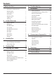
Contents 1. Before You Start... 1 6. Troubleshooting 19 Important! 1 Installation and Maintenance 1 7. Installation 21 Peculiar Smells 1 If you smell gas 1 Ventilation 1 Personal Safety 1 Cooker Care 2 Cleaning 2 2. 3.
ii
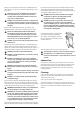
1. Before You Start... Your cooker should give you many years of trouble-free cooking if installed and operated correctly. It is important that you read this section before you start, particularly if you have not used a dual fuel cooker before. If you smell gas • • • • • • • Important! This appliance is designed for domestic cooking n only. Using it for any other purpose could invalidate any warranty or liability claim.
Always be certain that the controls are in the OFF position when the oven is not in use, and before attempting to clean the cooker. up and over the sides of the pan. Carefully watch for spills or overheating of foods when frying at high or medium high temperatures. Never try to move a pan of hot fat, especially a deep fat fryer. Wait until the fat is cool.
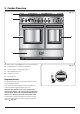
DocNo.020-0006 - Overview - 100DF - Prof+ 2. Cooker Overview Fig. 2.1 A Professional + 100 FX B C D E ArtNo.270-0029 - Prof+ 90SC annotated The 100 dual fuel cooker (Fig. 2.1) has the following features: A. 5 hotplate burners including a wok burner B. A control panel incorporating a timer C. Main multifunction oven D. Multifunction oven E. Storage drawer ArtNo.
Fig. 2.3 The igniter should spark and light the gas. Keep holding the knob pressed in to let the gas through to the burner for about ten seconds. ArtNo.270-0003 Proplus control to low If, when you let go of the control knob, the burner goes out, then the FSD has not been bypassed. Turn the control knob to the ‘OFF’ position and wait for one minute before you try again, this time making sure to hold in the control knob for slightly longer.
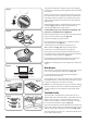
The Griddle Fig. 2.11 The griddle fits the left-hand pan support, front to back (Fig. 2.11). It is designed for cooking food on directly. DO NOT use pans of any kind on it. The griddle surface is non-stick and metal cooking utensils (e.g. spatulas) will damage the surface. Use heat resistant plastic or wooden utensils. DO NOT put it crossways – it will not fit properly and n will be unstable (Fig. 2.12). DO NOT put it on any other burner – it is not n designed to fit in any of the other pan supports.
The Multifunction Ovens Function Use Defrost To thaw small items in the oven without heat Fan oven A full cooking function, even heat throughout, great for baking Fanned grilling Grilling meat and fish with the door closed Fan assisted A full cooking function good for roasting and baking Conventional oven A full cooking function for roasting and baking in the lower half of the oven Browning element To brown and crisp cheese topped dishes Base heat To crisp up the bases of quiche, pizza or pa
Fanned Grilling This function operates the fan while the top element is on. It produces a more even, less fierce heat than a conventional grill. For best results place the food to be grilled on the pan provided. Thick pieces of meat or fish are ideal for cooking in this way, as the circulated air reduces the fierceness of the heat from the grill. The oven door should be kept closed while cooking is in progress, so saving energy.
The Ovens Fig. 2.15 The clock must be set to the time of day before the lefthand oven will work. See the following section on ‘The Clock’ for instructions on setting the time of day. The clock only controls the left-hand oven. ArtNo.270-002 Proplus o en controls 2 References to ‘left-hand’ and ‘right-hand’ ovens apply as viewed from the front of the appliance. Note: Please remember that all cookers vary so temperatures in your new ovens may differ to those in your previous cooker.
To Stop the Multifunction Oven at a Specific Time of Day ArtNo.301-000 2 Stopping the o en 2 Fig. 2.21 You have set the required temperature and function mode for the Multifunction Oven and you would like the Multifunction Oven to automatically stop. G TOP TIP A Make a note of the current time so you do not forget. B ArtNo.301-000 2 Stopping the o en 2 1. Turn the Timer (A) knob to the Stop Time (G) setting (Fig. 2.21). Fig. 2.22 2.
To Start and Stop the Multifunction Oven ArtNo.301-0010 2 Setting the coo ing time Fig. 2.25 The Multifunction Oven allows you to automatically start and stop by a combination of the length of the cooking time and the stop time. Giving you the flexibility to cook casseroles etc while you are out. You cannot set the actual start time. F A 1. Turn the Timer (A) knob to the Cook Time (F) setting. Turn the Adjusting (B) knob clockwise to set the length of the cooking time required e.g. 50 seconds (Fig. 2.
Key Lock Art No. 301-0011 2 Acti ating the e loc 1 The Key Lock will activate and deactivate the Multifunction Oven. 1. Cancel any active programs. Refer to ‘Reset to Manual Cooking’. Fig. 2.31 C 2. Turn the Timer (A) knob to the Clock (C) setting and hold for approx. 8 seconds. The display will show ‘ON’ (Fig. 2.31). A B ArtNo.301-0012 2 Acti ating the e loc 2 3.
Fig. 2.40 Storage Fig. 2.41 The bottom drawer is for storing oven trays and other cooking utensils. It can get very warm, so do not store anything in it that may melt or catch fire. Never store flammable materials in the drawer. This includes paper, plastic and cloth items, such as cookbooks, plastic ware and towels, as well as flammable liquids. Do not store explosives, such as aerosol cans, on or near the appliance. Make sure the inner rail is pulled Make sure forwards the inner rail is forwards Fig.
3. Cooking Tips Cooking with a Multifunction Oven General Oven Tips Remember: not all modes are suitable for all food types. The oven cooking times given are intended for a guide only. The wire shelves should always be pushed firmly to the back of the oven. Tips on Cooking with the Timer Baking trays with food cooking on them should be placed level with the front edge of the oven’s wire shelves. Other containers should be placed centrally.
DocNo.031-0004 - Cooking table - electric & fan single cavity 4. Cooking Table The oven control settings and cooking times given in the table below are intended to be used AS A GUIDE ONLY. Individual tastes may require the temperature to be altered to provide a preferred result. Food is cooked at lower temperature in a fan oven than in a conventional oven. When using recipes, reduce the fan oven temperature by 10 °C and the cooking time by 5-10 minutes.
5. Cleaning Your Cooker Essential Information Fig. 5.1 A Isolate the electricity supply before carrying out any thorough cleaning. Allow the cooker to cool. C NEVER use paint solvents, washing soda, caustic n cleaners, biological powders, bleach, chlorine based B bleach cleaners, coarse abrasives or salt. DO NOT mix different cleaning products – they may n react together with hazardous results.
Control Panel and Doors Fig. 5.5 Avoid using any abrasive cleaners including cream cleaners. For best results, use a liquid detergent. The same cleaner can be used on the doors, or alternatively, using a soft cloth wrung out in clean hot soapy water – but take care that no surplus water seeps into the appliance. After cleaning, polish with a dry cloth.
Removing the Right-hand Oven Shelf Supports Fig. 5.9 To clean the oven sides, slide out the shelves, unhook the shelf supports from the oven sides (Fig. 5.9), and lift out. Refit in reverse, making sure that the bottom of the shelf supports are inserted into the holes at the bottom of the oven (Fig. 5.10), prior to hooking the top into position. Removing the Right-hand Oven Cover Plate and Reflector Tray Isolate the electricity supply before carrying out any thorough cleaning. Allow the cooker to cool.
Cleaning Table Cleaners listed (Table 5.1) are available from supermarkets or electrical retailers as stated. For enamelled surfaces use a cleaner that is approved for use on vitreous enamel. Regular cleaning is recommended. For easier cleaning, wipe up any spillages immediately. Hotplate Part Finish Recommended Cleaning Method Hob top (including burner heads and Enamel, stainless steel, caps) aluminium Hot soapy water, soft cloth. Any stubborn stains remove gently with a nylon scourer.
6. Troubleshooting Hotplate ignition or hotplate burners faulty Is the power on? Is the clock illuminated? If not, there maybe something wrong with the power supply. Are the sparker (ignition electrode) or burner slots blocked by debris? Are the burner trim and caps correctly located? See the section on ‘Cleaning’? Hotplate burners will not light Make sure that the burner parts have been replaced correctly after wiping or removing for cleaning.
The timed oven is not coming on when automatic cooking Has the oven knob been left in the OFF position by mistake? Fig. 6.1 Is the oven locked (see above)? ArtNo.324-0005 Oven light bulb Oven temperature getting hotter as the cooker gets older If turning the temperature down using the oven control knob has not worked, or has only worked for a short time, then you may need a new thermostat. This should be fitted by a service person. Fig. 6.2 Oven lights are not working The bulb has probably burnt out.
INSTALLATION Check the appliance is electrically safe and gas sound when you have finished. 7. Installation Service and Spares Firstly, please complete the appliance details below and keep them safe for future reference – this information will enable us to accurately identify the particular appliance and help us to help you. Filling this in now will save time and inconvenience if you later have a problem with the appliance. It may also be of benefit to keep your purchase receipt with this leaflet.
INSTALLATION Check the appliance is electrically safe and gas sound when you have finished. Safety Requirements and Regulations Provision of Ventilation Please read the Before you start... chapter, before you begin any installation and maintenance work on this appliance. n This appliance is not connected to a combustion products evacuation device. Particular attention shall be given to the relevant requirements regarding ventilation.
INSTALLATION Check the appliance is electrically safe and gas sound when you have finished. You will need the following equipment to complete the cooker installation satisfactorily: • Flexible gas hose. • Gas pressure tester/manometer. • Multimeter: For electrical checks. Checking the Parts: 3 pan supports Griddle ArtNo.000-0001 90 Pan supports You will also need the following tools: 1. Electric drill 2. Masonry drill bit (only required if fitting the cooker on a stone or concrete floor) 3.
INSTALLATION Check the appliance is electrically safe and gas sound when you have finished. Positioning the Cooker Fig. 7.1 A The diagram (Fig. 7.1) shows the minimum recommended distance from the cooker to nearby surfaces as given in AS/NZS 5601. B C Where the appliance is installed next to cabinetry, the cabinet material must be capable of withstanding 70°C. If this appliance is installed near vinyl wrapped surfaces, use an installation kit available from the vinyl-wrap supplier.
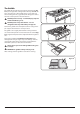
INSTALLATION Check the appliance is electrically safe and gas sound when you have finished. To help you, there are two levelling rollers at the back and two screw-down levelling feet at the front. Fig. 7.3 From the back tilt the cooker forward and remove the rear half of the polystyrene base pack (Fig. 7.2). Repeat from the front and remove the front half of the polystyrene base.
INSTALLATION Check the appliance is electrically safe and gas sound when you have finished. Fitting a Stability Bracket Fig. 7.6 Stability bracket When fitting a stability bracket please refer to the instructions supplied with the bracket for further details on fitting. When fitting a stability bracket (Fig. 7.6 and Fig. 7.7) adjust the bracket to give the smallest practicable clearance between the bracket and the engagement slot in the rear of the cooker.
INSTALLATION Check the appliance is electrically safe and gas sound when you have finished. Pressure Testing Fig. 7.10 The pressure test point is accessible on the inlet pipe at the rear. Remove the test nipple screw and fit a pressure gauge to the test point. Turn on and light two of the hotplate burners. For Natural Gas cookers the pressure should be between 0.95kPa and 1.0kPa. For Propane X cookers the pressure should be 2.54 kPa. ArtNo.
INSTALLATION Check the appliance is electrically safe and gas sound when you have finished. Fixed Wiring Fig. 7.14 For connection to fixed wiring, i.e. flexible conduit, remove the electrical terminal cover on the back panel. Fix the conduit-to-conduit mounting bracket onto the rear cover with screws (Fig. 7.13). Connect the mains cable to the correct terminals for your electrical supply type (Fig. 7.10 and Fig. 7.12). Check that the links are correctly fitted and that the terminal screws are tight.
WARNING – SERVICING TO BE CARRIED OUT ONLY BY AN AUTHORISED PERSON Disconnect from electricity and gas before servicing. Check appliance is safe when you have finished. 8. Conversion to Propane Gas Conversion from Natural Gas (1.0 kPa) to LPG X Propane (2.54 kPa) Fig.8.1 This conversion must be performed by a competent n person, in accordance with these instructions and with the local supply company requirements. Read the instructions before converting this appliance.
WARNING – SERVICING TO BE CARRIED OUT ONLY BY AN AUTHORISED PERSON Disconnect from electricity and gas before servicing. Check appliance is safe when you have finished. Set the Governor Fig.8.4 ArtNo.103-000 - a itrol cap Unscrew the governor’s brass top. In the base of the brass top is a plastic snap-in converter device (Fig.8.4). To convert the governor, snap the device out of the top and refit it the other way round. The snap-in converter device is marked to show the gas for which it is set (Fig.8.
WARNING – SERVICING TO BE CARRIED OUT ONLY BY AN AUTHORISED PERSON Disconnect from electricity before servicing. Check appliance is safe when you have finished. 9. Servicing BEFORE SERVICING ANY GAS CARRYING n COMPONENTS TURN OFF THE GAS SUPPLY Fig. 9.1 Check the appliance is gas sound after completion n of service. When checking for gas leaks DO NOT use washing up liquid – this can corrode. Use a product specifically manufactured for leak detection.
WARNING – SERVICING TO BE CARRIED OUT ONLY BY AN AUTHORISED PERSON Disconnect from electricity before servicing. Check appliance is safe when you have finished. Reassemble in reverse order, making sure that you reconnect the leads. Take care not to damage the burner ignition electrodes. IMPORTANT: Make sure you replace the rear earthing leads when refitting the fixing screws as they form part of the cooker earthing. Check for correct burner operation. 2.
WARNING – SERVICING TO BE CARRIED OUT ONLY BY AN AUTHORISED PERSON Disconnect from electricity before servicing. Check appliance is safe when you have finished. 4 Ovens Fig. 9.3 4.1 To Remove the Oven Inner Back Main Oven Only Open the main oven door. Remove the 4 screws and washers securing the inner back to the back of the oven (Fig. 9.3). Carefully lift away the inner back. Reassemble in reverse order, making sure that you fully tighten the 4 screws and washers. Standard burner B A C ArtNo.
WARNING – SERVICING TO BE CARRIED OUT ONLY BY AN AUTHORISED PERSON Disconnect from electricity before servicing. Check appliance is safe when you have finished. Top Element Fig. 9.7 Open the left-hand oven door and undo the fixings that secure the heat shield. Remove the top element bracket fixings and withdraw the element. Replace the element and reassemble parts in reverse order. Check that the oven operates satisfactorily. 4.
WARNING – SERVICING TO BE CARRIED OUT ONLY BY AN AUTHORISED PERSON Disconnect from electricity before servicing. Check appliance is safe when you have finished. 4.7 To Replace an Oven Thermostat Fig. 9.9 DISCONNECT FROM THE ELECTRICITY SUPPLY. n Remove the control panel (see 1.1) and hotplate top (see 2.1). Open the oven doors and remove the oven furniture. Left-hand oven A B Remove the four screws that secure the fan cover (Fig. 9.3) then remove the fan cover.
WARNING – SERVICING TO BE CARRIED OUT ONLY BY AN AUTHORISED PERSON Disconnect from electricity before servicing. Check appliance is safe when you have finished. 5 Fig. 9.10 Doors 5.1 To Replace an Oven Door Open the oven door fully and place the supplied holding pins in the drop down hinges (Fig. 9.10). Lift the door panel up and out. Carefully fit the new door panel and push down gently to release the holding pins. THE DOORS ARE HEAVY, SO TAKE CARE. n Fig. 9.11 5.
10.
DocAUS.102-0002 - Technical data - 90DF - Prof+ 11. Technical Data This cooker is designed for use on Natural Gas, although a conversion for LP (LPG X Propane (2.54 kPa) gas is packed with the cooker. INSTALLER: Please leave these instructions with the user. DATA BADGE LOCATION: Cooker back. The serial number is repeated on the badge below the left-hand oven door opening. COUNTRY OF DESTINATION: Australia. Connection & Test Pressures Gas (Rp ½ at rear right-hand side) Natural gas 1 kPa Propane 2.
Notes 38
Clarence Street, Royal Leamington Spa, Warwickshire, CV31 2AD, England. Tel: +44 (0) 1926 457400 Fax: +44 (0) 1926 450526 E-mail: consumers@falconappliances.co.