� ������������� �� ArtNo.000-0025 - Professional + FX logo Dual Fuel User Guide & Installation & Service Instructions ArtNo.
Contents 1. 2. 3. Before You Start... 1 7.
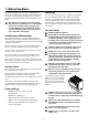
1. Before You Start... Ventilation Thank you for buying a Falcon cooker. It should give you many years of trouble-free cooking if installed and operated correctly. It is important that you read this section before you start, particularly if you have not used a dual fuel cooker before. The use of a gas cooking appliance results in the production of heat and moisture in the room in which it is installed.
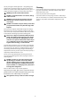
Cleaning Use dry oven gloves when applicable – using damp gloves might result in steam burns when you touch a hot surface. Do not use a towel or other bulky cloth in place of a glove – it might catch fire if brought into contact with a hot surface. NEVER operate the cooker with wet hands. NEVER heat unopened food containers. Pressure build up may cause the containers to burst and cause injury. DO NOT use unstable saucepans.
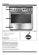
2. Overview DocNo.025-0101 - Overview - 90 DF SC - Prof+ FX Fig.2-1 � � Professional + FX � � ArtNo.270-0029 - Prof+ 90SC annotated The dual fuel single cavity cooker (Fig.2-1) has the following features: A. B. C. D. ArtNo.270-0001 Proplus control to high 5 hotplate burners including a wok burner A control panel incorporating a timer A multi-function oven A storage drawer Hotplate Burners The drawing by each of the central knobs indicates which burner that knob controls.
Fig.2-3 If, when you let go of the control knob, the burner goes out, then the FSD has not been bypassed. Turn the control knob to the OFF position and wait for one minute before you try again, this time making sure to hold in the control knob for slightly longer. ArtNo.270-0003 Proplus control to low Adjust the flame height to suit by turning the knob clockwise (Fig.2-3). If a burner flame goes out, turn off the control knob and leave it for one minute before relighting it.
The cradle will get very hot in use – allow plenty of time for it to cool before you pick it up. Fig.2-10 The Griddle The griddle fits the left-hand well, front to back (Fig.2-11). It is designed for cooking food on directly. DO NOT use pans of any kind on it. The griddle surface is non-stick and metal cooking utensils (e.g. spatulas) will damage the surface. Use heat resistant plastic or wooden utensils. DO NOT put it crossways – it will not fit properly and will be unstable.
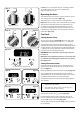
Fig.2-13 � Multi-function oven modes (Fig.2-13) ArtNo.270-0025 Proplus MF oven annotated Defrost � This function operates the fan(s) to circulate cold air ArtNo.030-0028 - Elan MF small symbolsitems such only. No heat is applied. This enables as desserts, cream cakes and pieces of meat, fish and poultry to be defrosted. OFF � � Defrosting in this way speeds up the process and protects the food from contamination.
Conventional Oven (Top and Base Heat) This function combines the heat from the top and Elan MF symbols base elements. It is particularly suitable for roasting and baking pastry, cakes and biscuits. ls WARNING! Take great care when removing the divider NOT to scratch the inner glass door surface. Scratches in the glass can cause stress and may cause the door to fail.
DO NOT place or slide metallic objects, including cookware, on the door glass as this may cause scratching and subsequent failure to occur. Fig.2-17 0 ArtNo.270-0026 Proplus MF oven controls (2) OFF Operating the Oven The multi-function oven has two controls: a function selector and a temperature setting knob (Fig.2-17). 0 10 22 0 Turn the function selector control to a cooking function. Fig.2-18 shows the control set for convectional oven cooking.
Once the ‘stop time’ is reached, the beeper sounds. Turn the Timer knob to the vertical () to return to manual cooking. Fig.2-25 ArtNo.301-0009 2BC Setting the cooking timer To start and then stop the oven using the Timer Fig.2-26 ArtNo.301-0010 2BC Setting the cooking time You cannot set a start time directly – this is set automatically by a combination of the ‘cook time’ and ‘stop time’. Turn the Timer knob to the () position (Fig.2-25).
Fig.2-33 Accessories Fig.2-34 Oven racks Each oven is supplied with: ArtNo.326-0013 - Full capacity shelf (Falcon) Two full capacity shelves (Fig.2-33) ArtNo.326-0004 - Cradle shelf Grill pan tray support (Fig.2-34) Two grill pans with trivets (Fig.2-35) Fig.2-35 Three energy saving shelves (Fig.2-36) Fig.2-36 Four ladder shelf supports (Fig.2-37) ArtNo.331-0008 - 90SC grill pan & trivet And one divider (Fig.2-38) ArtNo.326-0002 - Energy saving shelf Fig.
Storage Fig.2-42 The bottom drawer is for storing oven trays and other cooking utensils. It can get very warm, so do not store anything in it that may melt or catch fire. Never store flammable materials in the drawer. This includes paper, plastic and cloth items, such as cookbooks, plastic ware and towels, as well as flammable liquids. Do not store explosives, such as aerosol cans, on or near the appliance. ArtNo.
3. Cooking Tips Cooking with a Multi-function Oven Remember: not all modes are suitable for all food types. The oven cooking times given are intended for a guide only. General Oven Tips The wire shelves should always be pushed firmly to the back of the oven. Baking trays with food cooking on them should be placed level with the front edge of the oven’s wire shelves. Other containers should be placed centrally.
4. Cooking Table DocNo.031-0004 - Cooking table - electric & fan single cavity The oven control settings and cooking times given in the table below are intended to be used AS A GUIDE ONLY. Individual tastes may require the temperature to be altered to provide a preferred result. Top Centre Food is cooked at lower temperature in a fan oven than in a conventional oven. When using recipes, reduce the fan oven temperature by 10°C and the cooking time by 5-10 minutes.
5. Troubleshooting Steam is coming from the oven When cooking foods with a high water content (e.g. oven fries) there may be some steam visible at the rear grille. Take care when opening the oven door, as there may be a momentary puff of steam when the oven door is opened. Stand well back and allow any steam to disperse. If two racks are used, check that space has been left for the heat to circulate. When a baking sheet is put into the oven, make sure it is placed centrally on the rack.
Hotplate ignition or cooktop burners faulty Is the power on? Fig.5-1 Are the sparker (ignition electrode) or burner holes blocked by debris? ArtNo.324-0005 Oven light bulb Are the burner heads correctly located? See the section entitled ‘Cleaning’. Remember that each cooktop burner has a special safety device that stops the flow of gas if the flame goes out. When lighting a cooktop burner the safety device has to be overridden by holding in the control knob so that the gas can flow.
6. Cleaning Your Cooker Isolate the electricity supply before carrying out any major cleaning. Allow the cooker to cool. Fig.6-1 � Never use paint solvents, washing soda, caustic cleaners, biological powders, bleach, chlorine based bleach cleaners, coarse abrasives or salt. Do not mix different cleaning products – they may react together with hazardous results. � � All parts of the cooker can be cleaned with hot soapy water – but take care that no surplus water seeps into the appliance.
Hotplate Burners � The burner heads and caps can be removed for cleaning. Make sure they are absolutely dry before replacing. The Single Ring Burners ArtNo.311-0014 Wok burner details Fig.6-2 � When refitting the burner head, ensure that the notch lines up with the electrode or hole in the base. Check that the burner head is level and that the cap is fitted centrally on the burner head (Fig.6-1). � The Wok Burner When reassembling the wok burner (Fig.
Cleaning Table Cleaners listed are available from supermarkets or electrical retailers as stated. Cleaner manufacturer in Italics. For enamelled surfaces use a cleaner that is approved for use on vitreous enamel. Regular cleaning is recommended. For easier cleaning, wipe up any spillages immediately. To help keep your oven clean, cover meat when roasting, with foil or use a roasting bag. Brush vegetables with fat before placing around the meat.
INSTALLATION Check the appliance is electrically safe and gas sound when you have finished. 7. Installation Service and Spares Firstly, please complete the appliance details below and keep them safe for future reference – this information will enable us to accurately identify the particular appliance and help us to help you. Filling this in now will save time and inconvenience if you later have a problem with the appliance. It may also be of benefit to keep your purchase receipt with this leaflet.
INSTALLATION Check the appliance is electrically safe and gas sound when you have finished. Dear Installer Provision of Ventilation Before you start your installation, please complete the details below, so that, if your customer has a problem relating to your installation, they will be able to contact you easily. This appliance is not connected to a combustion products evacuation device. Particular attention shall be given to the relevant requirements regarding ventilation.
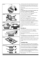
INSTALLATION Check the appliance is electrically safe and gas sound when you have finished. You will need the following equipment to complete the cooker installation satisfactorily: • Restraining chain: If the cooker is to be supplied with gas through a flexible hose, a restraining chain must be fitted. • Flexible gas hose. • Gas pressure tester/manometer • Multimeter: For electrical checks Checking the Parts: You will also need the following tools: 1. 2. 4. 5. 6. 7. 8. 9. 10.
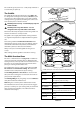
INSTALLATION Check the appliance is electrically safe and gas sound when you have finished. Positioning the Cooker Fig.7-1 The diagram (Fig.7-1) shows the minimum recommended distance from the cooker to nearby surfaces as given in AS 5601. 1. � � The minimum height of any surface above the cooker is 650mm above the hotplate. � � � Overhead – Measurement A Range hoods and exhaust fans shall be installed in accordance with the manufacturer’s instructions.
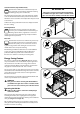
INSTALLATION Check the appliance is electrically safe and gas sound when you have finished. Removing the Storage Drawer Fig.7-2 Pull the drawer out to its furthest point (Fig.7-2). Lift up the ends of the plastic clips (one each side) to release the catches holding the drawer to the side runners and at the same time pull the drawer forward and away from the side runners (Fig.7-3). ArtNo.281-0138 - Drawer pulled out For safety’s sake push the drawer runners back out of the way.
INSTALLATION Check the appliance is electrically safe and gas sound when you have finished. Stability Bracket and Chain Fig.7-7 � � � Unless properly installed, the cooker could be tipped by leaning on the door. Injury might result from spilled hot liquids or from the cooker itself. � IMPORTANT: The cooker must be set to the correct height and levelled before the stability bracket is installed. ArtNo.280-0032 - Assembling the Anti-tip bracket Floor Attachment Fig.
INSTALLATION Check the appliance is electrically safe and gas sound when you have finished. Gas Connection Fig.7-12 Must be in accordance with the relevant standards. �� The gas supply needs to terminate with a down facing bayonet. �� ��� Because the height of the cooker can be adjusted and each connection is different it is difficult to give precise dimensions. The hose should be fitted so that both inlet and outlet connections are vertical so that the hose hangs downwards in a ‘U’ shape (Fig.7-12).
INSTALLATION Check the appliance is electrically safe and gas sound when you have finished. Electrical Connection Fig.7-13 This appliance must be installed by a qualified electrician to comply with the relevant regulations (AS/NZS 60335.2.6:2002) and also the local electricity supply company requirements. Ensure that the mains characteristics (voltage, nominal, power, etc.) match the ratings indicated on the data plate affixed to the cooker. ArtNo.
INSTALLATION Check the appliance is electrically safe and gas sound when you have finished. Oven Check Fig.7-17 Turn on the oven and check that it starts to heat up. Check that the oven lights are working. Note: The oven light bulb is not included in the guarantee. Turn off the oven. ArtNo.281-0026 - Front plinth Fitting the Plinth Remove the 3 screws for the plinth mounts along the front bottom edge of the range (Fig.7-17).
WARNING – SERVICING TO BE CARRIED OUT ONLY BY AN AUTHORISED PERSON Disconnect from electricity and gas before servicing. Check appliance is safe when you have finished. 8. Conversion to Propane Gas DocNo.071-0003 - LP gas conversion - 90 single cavity Check in the ‘Technical Data’ section at the back of these instructions that the cooker is convertible to the type of gas you want to use. Fig.
WARNING – SERVICING TO BE CARRIED OUT ONLY BY AN AUTHORISED PERSON Disconnect from electricity and gas before servicing. Check appliance is safe when you have finished. Set the Governor Fig.8-5 Unscrew the governor’s brass top. In the base of the brass top is a plastic snap-in converter device (Fig.8-5). To convert the governor, snap the device out of the top and refit it the other way round. The snap-in converter device is marked to show the gas for which it is set (Fig.8-6). ArtNo.
WARNING – SERVICING TO BE CARRIED OUT ONLY BY AN AUTHORISED PERSON Disconnect from electricity and gas before servicing. Check appliance is safe when you have finished. 9. Servicing Fig.9-1 BEFORE SERVICING ANY GAS CARRYING COMPONENTS. TURN OFF THE GAS SUPPLY DO NOT modify this appliance! Check the appliance is gas sound after completion of service. When checking for gas leaks DO NOT use washing up liquid – this can corrode. Use a product specifically manufactured for leak detection.
WARNING – SERVICING TO BE CARRIED OUT ONLY BY AN AUTHORISED PERSON Disconnect from electricity and gas before servicing. Check appliance is safe when you have finished. 4. To Change Oven or Light Switch Fit the replacement in reverse order. Disconnect the cooker from the electricity supply. Ensure the phial is clipped securely to the oven rear cover. Remove the control panel (see 1). To change the protect thermostat Note: The old switch may be destroyed during removal.
WARNING – SERVICING TO BE CARRIED OUT ONLY BY AN AUTHORISED PERSON Disconnect from electricity and gas before servicing. Check appliance is safe when you have finished. 11. To Remove a Hotplate Burner Thermocouple Fig.9-5 Disconnect the cooker from the electricity supply. Remove the hotplate (see 2). Identify the thermocouple to be removed. Pull off the connection at the tap end and lift the thermocouple away at the burner end. ����� Fit the new thermocouple in the reverse order. Replace the hotplate.
WARNING – SERVICING TO BE CARRIED OUT ONLY BY AN AUTHORISED PERSON Disconnect from electricity and gas before servicing. Check appliance is safe when you have finished. Lift out the inner panel and place it, outer side up, on a clean level surface. Undo the screws securing the hinge in place. Remove the hinge. Replace the hinge and rebuild the door in the reverse order. Fig.9-8 17. To Remove the Oven Door Seal Open the oven door. The seal is held in place by small hooks to the cooker front.
WARNING – SERVICING TO BE CARRIED OUT ONLY BY AN AUTHORISED PERSON Disconnect from electricity and gas before servicing. Check appliance is safe when you have finished. 21. To Remove the Oven Bottom and Top Elements Fig.9-12 Disconnect the cooker from the electricity supply. Bottom Element Pull the cooker forward to access the cover boxes at the rear of the cooker. Remove the fixings that secure the cover and lift it clear. � Remove the 2 screws ‘A’ and allow the plate to drop down.
35 ��� � �� � � � � � �� �� ����� ����� � � � � � ����������� � � � � � � � � � � � � � � � � � � �� � � � ����������� � �� � ����� ����� ArtNo.
11. Technical Data This cooker is designed for use on natural gas but can be converted to LP (Propane X (2.54kPa). A conversion kit from Natural Gas to Propane is supplied with the cooker. Installer: Please leave these instructions with the user. DATA BADGE LOCATION: Inside base drawer of cavity and on rear of the appliance. COUNTRY OF DESTINATION: Australia Connections Gas Rp½ at right rear Electric 1kPa 240V 50Hz Natural Gas Propane 2.
37
ArtNo.000-0001 Aga address block ArtNo.