
Power Supply User Manual

CHAPTER
CHAPTER
5
5
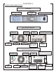
COMMUNICATIONS INTERFACES
RS-232 INTERFACE
15
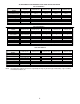
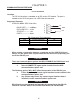
Pin #
Function explanation
I/O
9
RS 232 Rx
INPUT
6
RS 232 Tx
OUTPUT
7
Ground
Location:
The RS-232 interface is standard on all SG series UPS models. The port is
located on the UPS rear panel, via a DB-9 female connector.
Supported Protocols
UPSILON 2000 & SEC Smart Mon
BAUD RATE ------- 2400bps
DATA LENGTH---- 8 bits
STOP BIT----------- 1 bit
PARITY-------------- None
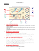
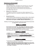
DB-9 Connector Pin Assignment
When making a connection between a computer and the UPS RS-232 port,
always use the green cable supplied with the UPS due to the propriatary pin-
out of the RS-232 port.
There are communications options that WILL
DISABLE the RS-232 port and
render it inoperable. The options are as follows:
a. Internal SNMP/HTTP agent option installed into the UPS
communications option slot.
The following options WILL
NOT affect the operation of the RS-232 port:
a. Falcon Opto Coupler based signal interface board installed in the
communications option slot.
b. Any Falcon relay based, dry contact signal interface board
installed in to the communications option slot.
DB-9 Signals are not isolated and intended for connection to like RS-232
interfaces. DO NOT APPLY ANY OTHER VOLTAGES TO THESE PINS!
6
7
8
9
1
2
3
4
5
TX
RX
GEN
CAUTION
CAUTION
CAUTION
GND