OWNER'S OPERATING MANUAL FN SeriesTM Rackmount UPS Plus® Parallel or N+1 Redundant 3kVA to 24kVA Hardwire models with a 208-240Vac Input and 120Vac & 240Vac Outputs Uninterruptible Power Supply Models: FN3KRM-2, -2TX & -2TXI FN4KRM-2, -2TX & -2TXI FN5KRM-2, -2TX, & -2TXI FN6KRM-2, -2TX & -2TXI FALCON® Electric, Inc., 5106 Azusa Canyon Rd., Irwindale, California 91706, (626) 962-7770, Fax (626) 962-7720, Email: sales@falconups.com 2009 Falcon® Electric Inc. All rights reserved.
TABLE OF CONTENTS FN Rackmount Series Parallelable and N+1 Redundant UPS Features.. . . . FN -2TXI Double-Conversion On-line UPS Block Diagram. . . . . Important Safety Instructions (READ FIRST) . . . . . Chapter 1. Introduction 1.1 Manual Overview. . . . . . . 1.2 Brief FN Overview. . . . . . . Chapter 2. FN UPS Circuit Descriptions Galvanically Isolated Output. . . . . . Input & Power Factor Correction . . . . . Power Factor Correction. . . . . . DC/DC Converter. . . . . . . . DC/AC Inverter . . . . . .
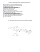
FN SeriesTM Parallelable and N+1 Redundant UPS Features Parallel Mode and N+1 Redundant Mode Operation True Double Conversion On-Line Sinewave Design Output Galvanic Isolation LCD Display with Advanced Monitoring Remote Emergency Power Off (REPO) Option Input Power Factor Correction Wide Input Voltage Window Precision Output Voltage Regulation Superior Brownout, Surge and Transient Protection Frequency Converter Operation User-Replaceable and Hot-Swappable Battery Pack Optional Extended Battery Banks & Char
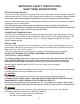
IMPORTANT SAFETY INSTRUCTIONS, SAVE THESE INSTRUCTIONS RETAIN THIS USER MANUAL! This manual contains important instructions which must be followed during the installation, operation and maintenance of the FN Series UPS, battery banks transformer box and options. Please read all instructions before operating this equipment and save this manual for future reference. All of the models presented herein are designed for installation and use in a temperature-controlled environment, free of contamination.
1.0 INTRODUCTION Manual Overview This user manual has been written to provide basic information about Falcon FN Series -2TXI rackmount models. The FN Series is a rugged, double conversion, "on-line" UPS. It has galvanic output isolation configured for single or dual voltage output(s). The FN Series provides continuous power conditioning and accepts a wide range input voltage, while providing tight voltage regulation and a true sinewave output.
g. One Local Maintenance Bypass Switch. The switch is located on the transformer module rear panel and provides a manual means of placing the UPS into bypass mode to allow for servicing to be performed on the UPS and battery modules. 2.0 FN RACKMOUNT UPS CIRCUIT DESCRIPTIONS Galvanically Isolated Output The FN -2TXI output isolation transformer module provides a galvanically isolated, 120/240Vac, hardwire output.
Battery Packs FN rackmount battery modules utilize flame retardant batteries. They consist of (20) 12V, 7AH valve-regulated, sealed lead acid (VRLA) batteries in each module (Yuasa NP7-12). See replacement instructions on page 34. To maintain the optimum battery life, the UPS should be installed in an environment with an ambient temperature of 68ºF to 77ºF (20ºC to 25ºC).
3.0 UNPACKING THE UPS AND BATTERY BANK Due to their size and weight the FN rackmount UPS, battery and transformer modules are packaged inside shipping cartons that are secured to a shipping pallet. Removal of the UPS, transformer and battery bank modules should never be attempted by one person. Upon unpacking the UPS, transformer or battery bank, verify the following items were shipped.
4.0 PRE-INSTALLATION DETAILS Falcon Electric, Inc. is not responsible for shipping damage or for filing shipping damage claims. Visually inspect the equipment for freight damage. If any equipment has been damaged during shipment, retain the shipping pallet and packing materials for inspection by the carrier, and immediately file a claim for “shipping damage” with the carrier. If you discover damage after acceptance, file a claim for “concealed damage”.
4.2 UPS Input Power Requirements a. FN3KRM-2TXI FN4KRM-2TXI FN5KRM-2TXI FN6KRM-2TXI VERIFY THE PROPER UPS INPUT POWER IS AVAILABLE (for each UPS installed) Input Input Input Input ----- Hardwire, Hardwire, Hardwire, Hardwire, 208-240Vac, 208-240Vac, 208-240Vac, 208-240Vac, 50/60Hz, 50/60Hz, 50/60Hz, 50/60Hz, 20A, 30A, 30A, 40A, single-phase, single-phase, single-phase, single-phase, 2 2 2 2 wire wire wire wire plus plus plus plus ground ground ground ground 4.3 UPS Input/Output Requirements a.
4.4 UPS Output Rating Details a. VERIFY THE LOAD TO BE CONNECTED DOES NOT EXCEED THE UPS OUTPUT RATING for the single or combined paralleled UPS units.
4.6 Output Transformer Module Hardwire Terminal Block Wiring Details 4.
4.8 System Installation Wiring Diagram (single rackmount UPS system) 4.9 System Installation Wiring Diagram (typical multiple parallel UPS units, Rackmount) 4.10 UPS & Transformer Modules Communications Bus Cabling Use one UA88385 parallel communications bus cabling kit for each UPS to be connected to the system output transformer module or to paralleled UPS systems. Connect the supplied cables as shown below.
4.
5.0 DISPLAY & CONTROLS The pictures below outline the various control panel, LED and LCD functions and locations. 5.1 Control Button and LCD Locations 1. LCD Display 2. N+1 Status LED 3. Utility Status Indicator LED 4. Bypass Input Status LED 5. UPS On / Alarm Silence Control Button 6. Previous Page / Change Setting Button 7. Confirm Button 8. Next Page Button 9. UPS Off / Bypass Button 10. Function Button 11. Economy/Green Mode Status LED 12. UPS Alarm LED 5.
Next Page Button 1. 2. 3. When the LCD display is in “Normal Mode”, repeated pressing of this button will sequence down through the input/output/battery parameters and readings. When the UPS is displaying “OFF” or “BPS”, depressing the “Next Page” and “Function” buttons at the same time will place the UPS into “Programming Mode”. Refer to the “How to Change the Programmed Settings” section of this manual for more details.
5.4 LCD Display Overview LCD Display Shown in Test Mode 5.5 LCD Icon Descriptions 1. Bypass input is out of tolerance, UPS failed to transfer to bypass, or bypass input is out of tolerance when the UPS is in Economy/Green Mode. 2. Utility loss or the utility input is out of tolerance. 3. UPS lost inverter output and transferred to bypass. 4. Battery voltage is out of tolerance, or defective batteries. 5. The UPS output is overloaded. 6. The UPS is presently in maintenance mode. 7.
Er04 -Er05 -Er06 -- Er07 Er08 Er09 Er10 ----- Er11 -Er12 -- Er13 Er14 Er15 Er18 Er22 Er24 ------- Er26 -Er28 -Er29 -Er** -- Error code 04 indicates the UPS inverter has malfunctioned. Contact Falcon Service. Error code 05 indicates the UPS batteries are weak or dead and must be replaced. Call Falcon Service upon receiving the message for further instructions. Error code 06 indicates the UPS output has a short circuit connected to it.
6.0 OPERATION The following sections outline the operation and programming of the FN -2TXI UPS models. Please read and understand them completely prior to connecting any equipment to the UPS output. 6.1 How to start up the UPS with utility power present 1. Verify the UPS input wiring is correct and connected to a live circuit. 2. Turn on the UPS and Bypass input circuit breakers located on the UPS rear panel, and the following LCD Display will be displayed.
If the UPS passes the self-test, “OK” is displayed. If the UPS fails the self-test, “FAIL” is displayed alternately with an error code. Please note the error code and contact Falcon Service. The UPS is now turned on and in on-line inverter mode. Using an AC volt meter, verify the UPS input voltage measurement.
6.2 How to start up the UPS without utility power present (Cold Start) 1. Press the “On” button for 6 seconds to awaken the UPS. The UPS will beep twice and display G below. Immediately upon G being displayed, press the “On” button for another 6 seconds. The UPS will beep twice again and sequence through H and I. After depressing the “On” button for 6 seconds the first time, the UPS will beep twice and “OFF” or “BPS” will be displayed.
6.5 How to display readings 1. The bypass input voltage is displayed immediately after the UPS and Bypass circuit breakers are turned on and has sequenced up to inverter mode as shown in I1. Depressing the “Next Page” button will change to display the utility frequency as shown in J below. The “b” denotes the reading is for the bypass. The arrow under the LINE indicates the reading is for the bypass input voltage. Depress the “Next Page” button. The “r” denotes the reading is for utility.
Depress the “Next Page” button. The arrow next to the battery icon indicates the reading is for the battery voltage. Depress the “Next Page” button. The degree C symbol indicates the reading is for the internal UPS temperature. Depressing the “Next Page” button again will return the display to reading I1.
6.6 How to Display Programmed Settings 1. The UPS must be turned on and operating in on-line inverter mode prior to attempting to read the “programmed settings”. 2. Depress the “Function” button and the following first function parameter will be displayed: The first function status displayed will be the audible alarm buzzer status. It is shown here to be turned on. If the “Previous Page/Change Setting” button is pressed, the audible alarm will be turned off.
Note: The following functions are a continuation from the previous page. These functions can only be displayed and must have their settings changed using another programming method referenced later in the manual. As the other programming method requires turning the UPS off to perform, they are accessible here as a convenient reference while the UPS is in normal online operation. The next parameter displayed shows the “bypass input voltage acceptable window” setting.
Fixed or constant frequency output mode: In normal mode the UPS output frequency will automatically be set to the utility frequency and is synchronized with that frequency. When set to cf50Hz mode, the UPS inverter output frequency will always be 50Hz. When set to cf60Hz mode, the UPS inverter output frequency will always be 60Hz. Setting the UPS to a fixed or constant output frequency should be done when the input source is a generator. Depress the “Next Page” button.
6.7 How to Change the Programmed Settings Note: The UPS must be placed into Off / Bypass mode prior to attempting to change the following parameter settings. 1. To enter programming mode depress the “On” and “Next Page” buttons at the same time and hold them down until the UPS sounds two beeps. The audible alarm status parameter setting will be displayed. The audible alarm parameter settings cannot be set in this programming mode. Refer to section 6 of this manual for setup instructions.
The next parameter displayed shows the “bypass input voltage acceptable window” setting. The voltage window can be set to “Lo” (184-260Vac) or “Hi” (195-260Vac), which is shown below. To change the settings, depress the “Previous Page/Change Setting” button. To change to the alternate setting, press the button again. All setting changes will be saved when prompted at the end of the parameter sequence. Depress the “Next Page” button. The next parameter displayed shows the acceptable input frequency window.
The following V1, V2, V3 and V4 show the operational status setting of the UPS. This function may be set to one of four modes. “Normal”: which indicates none of the other modes are set. The Economy/Green Mode: indicates the UPS will automatically transfer to bypass mode to save energy, should the output load drop below 10% of the UPS output rating.
The next parameter displayed shows the UPS unit address. If only one UPS is being used, the address should be set to “d0” as shown. X If multiple parallel UPS units are connected on a parallel configuration of 6, 12, 18 or 24kVA, or 6, 12, 18kVA N+1 operation, the units would be addressed “d0”, “d1”, “d2” and “d3”. See the parallel mode configuration section of this manual for more details. To change between these settings, depress the “Previous Page/Change Setting” button.
6.8 How to Use the Maintenance Bypass Switch Located on the Rear Panel IMPORTANT: Improper use of the internal Maintenance Bypass Switch will void the equipment warranty. The following instructions must be followed whenever this switch is used. 1. Press the”Off/Bypass” button for 5 seconds to place the UPS into bypass mode. 2. On the rear of the transformer module, remove the two phillips screws securing the upper and lower sides of the maintenance bypass security cover plate. 3.
7.0 COMMUNICATIONS All FN models are provided with the following communication ports: RS-232 port with standard DB-9F serial port connector located on the UPS module rear panel. Two advanced communications option slots are provided on the rear panel of the UPS module. Unless an advanced communications option board has been previously purchased and installed, the port will be covered with a small cover plate. This plate will be secured with (2) screws.
The supplied Falcon RS-232 interface cable pin designations are as follows: UPS Side RS-232C Interface Computer Side The computer RS-232 Port settings should be set to the following: 7.3 Optional Remote Emergency Power Off (REPO) A two-pin REPO connector (green connector) is located on the UPS module rear panel. The connector is shipped with no jumper wire installed, and is a normally open interface requiring a CLOSED EPO connection to initiate EPO UPS shutdown.
UA88382 USB Interface Option Card This option card supports the connection of (1) USB interface cable for use with UPSilon remote monitoring, management and unattended O/S shutdown software. 2 1 3 4 Pin Pin Pin Pin 1 2 3 4 - VCC (+5V) DD+ Ground Pin 1 - REPO 1 Pin 2 - REPO2 CN1 1 2 UA88383 Dry Contact Interface Option Card This card provides dry contact closure signals for UPS on bypass, utility normal, inverter on, low battery, abnormal battery, UPS summary alarm.
8.0 MAINTENANCE The FN Series UPS requires very little maintenance. The batteries are located inside the battery module and consist of (20) Yuasa 12V, 7AH or equivalent, sealed, VRLA, maintenance-free, lead-acid batteries. Batteries must be kept recharged to prevent excessive self-discharging, which may result in their premature failure. When connected to the battery module, the UPS will continuously recharge the batteries when plugged in and turned on.
9.0 PARALLEL MODE OPERATION 9.1 How to configure FN rackmount models for transformer module, parallel or N+1 mode operation. Up to (4) like kVA FN model UPS units may be connected to their respective transformer modules and/or in parallel, in single UPS increments, to provide a single 3-24kVA UPS output a true N+1 redundant output. This is accomplished by connecting each UPS to be paralleled, wired to a single utility source rated for the combined UPS load. The UPS outputs should be connected together.
10.0 ENVIRONMENTAL 10.1 Recycling the Used Battery Packs NEVER discard the UPS module, the UPS battery module, the transformer module or batteries in the trash. Contact your local recycling or hazardous waste center for information on proper disposal of the used battery pack and batteries. The entire spent battery packs may be returned to the Falcon Service Center at the end user’s expense for recycling.
11.0 TECHNICAL SUPPORT In the event your FN Series UPS requires service or should any other technical support be required, write, call, fax or email Falcon Service. Falcon Electric, Inc. 5106 Azusa Canyon Road Irwindale, CA. 91706 Service 800.842.6940 Voice 626.962.7770 Fax 626.962.7720 Email: service@falconups.com WWW.FALCONUPS.COM Please have your UPS model, serial number and date of purchase on hand prior to your call. This information is located on the identification label on the rear panel of the UPS.
FALCON ELECTRIC, INC. NEW PRODUCT LIMITED WARRANTY Limited Warranty: Falcon warrants that this product will be free from defects in materials and workmanship for a period of two years from the date of shipment by Falcon. Procedures: Any defective product must be returned to Falcon. No product can be returned without first obtaining a Return Material Authorization (RMA) number from Falcon.
FN SeriesTM UPS PLUS® 3kVA - 12kVA Falcon Electric, Inc. - 5106 Azusa Canyon Rd. - Irwindale, CA 91706 - 800.842.6940 Fax 626.962.7720 www.falconups.com - email: sales@falconups.
FN SeriesTM UPS PLUS® 4kVA - 16kVA Falcon Electric, Inc. - 5106 Azusa Canyon Rd. - Irwindale, CA 91706 - 800.842.6940 Fax 626.962.7720 www.falconups.com - email: sales@falconups.
FN SeriesTM UPS PLUS® 5kVA - 20kVA 42
FN SeriesTM UPS PLUS® 6kVA - 24kVA Falcon Electric, Inc. - 5106 Azusa Canyon Rd. - Irwindale, CA 91706 - 800.842.6940 - Fax 626.962.7720 www.falconups.