OWNER'S OPERATING MANUAL Uninterruptible Power Supply Models: SG800-1, SG800-2 SG1K-1T, SG1K-2T SG2K-1T, SG2K-2T, SG2K-2TXI SG3K-1T, SG3K-2T, SG3K-2TX Detailed SG Series product specifications are available in PDF format at www.falconups.com FALCON® Electric Inc., 5106 Azusa Canyon Rd., Irwindale, California 91706, (626) 962-7770, Fax 626-962-7720, Email: sales@falconups.com 2003 Falcon® Electric Inc. All rights reserved. All other brand names and trademarks are the property of their respective owners.
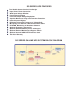
TABLE OF CONTENTS SG UPS Features. . . . SG Series Online UPS Block Diagram. . Important Safety Instructions (READ FIRST) . . . . . . . . . . 1 1 2 Chapter 1. SG Series UPS Overview . True Regenerative Online Design Input Power Factor Correction Microprocessor Control . SNMP/HTTP Remote Management Extended Battery Bank Option Frequency Converter Option . . . . . . . . . . . . . . . . . . . . . . 3 3 3 3 3 3 3 Chapter 2. Installation Instructions . . . Dip Switch Settings DIagrams . .
SG SERIES UPS FEATURES True Double Conversion On-Line Design Input Power Factor Correction Wide Input Voltage Window Pure Sinewave Output Precision Output Voltage Regulation Superior Brownout, Surge and Transient Protection Internal System Bypass Eliminates Generator Frequency & Voltage Drift Microprocessor Control & RS-232 Communications UPSILON® Monitoring & Shutdown Software Optional Frequency Conversion Optional Extended Battery Packs & Chargers Optional External Maintenance Bypass Switch Optional Inter
IMPORTANT SAFETY INSTRUCTIONS SAVE THESE INSTRUCTIONS This manual contains important instructions which must be followed during the installation, operation and maintenance of this UPS and its batteries. Please read all instructions before operating this equipment and save this manual for future reference. CAUTION All of the models presented herein are designed for installation and use in a temperature controlled environment, free of contamination. CAUTION This UPS utilizes voltage that may be hazardous.
CHAPTER 1 SG Series UPS - Overview True Regenerative On-Line Design As new and innovative technologies have become the backbone of today's businesses, maximum system availability is critical and downtime is more expensive than ever. Increasingly, businesses need a UPS that not only protects against blackouts, but also virtually eliminates more frequent and subtle power disturbances. Surges, sags, line noise and brownouts can disrupt proper operation of sensitive equipment.
CHAPTER 2 INSTALLATION INSTRUCTIONS 1. Verify the following is included in the UPS shipping carton: (1) UPS, (1) Software Diskette(s) & Manual, (1) Power Cord (800VA-1KVA models only), (1) Owners Manual & (1) UPS/Computer Cable. 2. Verify the UPS unit is configured for the proper input/output voltage and frequency. This information is stated on the nameplate label located on the rear or the side panel of the unit.
5. For SG800 - SG1K models, connect the power cord to the UPS inlet located on the UPS rear panel. On SG1.5K - SG3K models the line cord is permanently attached to the UPS. 6. Select a suitable location for the UPS near enough to the computer or equipment to to be protected. Connect the power cord(s) for the equipment to be protected to the UPS output receptacles. VERIFY THE TABLE OR SURFACE SUPPORTING THE UPS WILL SUPPORT THE WEIGHT OF THE UPS AND ANY OPTIONAL EXTENDED BATTERY BANKS.
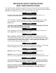
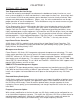
VIEW OF DIP SWITCHES LOCATED ON THE UPS REAR PANEL OFF = 0 DIP SWITCHES ON = 1 SELECTION TABLE SWITCH SETTINGS FOR -1 MODELS SW2 Down Down Up Up SW1 Down Up Down Up VOLTAGE 100V 110V 120V (Factory default) 115V SWITCH SETTINGS FOR -2 MODELS SW2 Down Down Up Up SW1 Down Up Down Up VOLTAGE 220V 230V (Factory Default) 240V 200V GREEN MODE SWITCH SETTINGS FOR ALL MODELS SW3 Down Up FUNCTION GREEN MODE ON GREEN MODE OFF 6
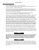
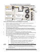
TYPICAL EXTENDED BATTERY BANK & UPS INTERCONNECTION (Mini-tower models shown; same applies for floor standing banks) TYPICAL BATTERY CONNECTOR 1ST CABLE TO ADD MORE BANKS, DAISY CHAIN TO NEXT BANK FROM THIS 2ND CABLE UPS BATTERY FUSE OPTIONAL BATTERY CHARGER CIRCUIT BREAKER POWER INLET FOR OPTIONAL CHARGER 2ND BATTERY BANK OPTIONAL BATTERY CHARGER CIRCUIT BREAKER POWER INLET FOR OPTIONAL CHARGER 1ST BATTERY BANK UPS INSTALLATION PROCEDURE FOR EXTENDED BATTERY BANKS 1. 2. 3.
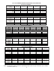
SG 1-3kVA TOWER EXTENDED BATTERY BANK SELECTION GUIDE FOR 800VA-1KVA MODELS BATTERY OPTION MODELS W/O Charger BATTERIES BATTERIES IN UPS # of CASES Inches (mm) RUN TIME @ 100W RUN TIME @ 200W RUN TIME @ 400W RUN TIME @ 700W BATTERY OPTION MODELS With 120Vac Charger BATTERY OPTION MODELS With 200-240Vac Charger CHARGER OUTPUT # OF CHARGERS SGB2S7-1K3 SGB4S7-1K3 6 Pieces 12V, 7AH 12 Pieces 12V, 7AH 1 Mini-Tower 13.8 x 7.6 x 18.9 (350 x 193 x 480) 215 Min. 107 Min. 49Min. 23Min.
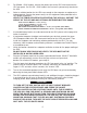
CHAPTER 3 OPERATION UPS FRONT PANEL INDICATOR AND FUNCTION KEYS 9 1 10 2 8 3 11 4 5 1. 6 7 LOAD LEVEL INDICATOR LEDS *The first or bottom LED is lit when the output load is greater than 25% of the rated output of the UPS. *The second LED is lit when the output load is greater than 50% of the rated output of the UPS. *The third LED is lit when the output load is greater than 75% of the rated output of the UPS. 2.
5. BYPASS INDICATOR LED When this LED is lit the UPS bypass is active. Should the Alarm LED be lit at the same time, the UPS detected an internal failure and the UPS must be serviced. 6. INVERTER INDICATOR LED When this LED is lit, the UPS inverter is operating and powering the connected load. 7. GREEN MODE LED INDICATOR 8.
AUDIBLE ALARMS Audible alarm signals are divided into two different levels of alarm status. Category one alarms represent normal or correctable operational alarms. Category two alarms are sounded in the event of abnormal operation. 1. Category one alarms: a. Two short beeps followed by three short beeps. Notifies the user that the SG UPS is configured with the optional battery pack and is in BATTERY MODE. - - - - - = SG UPS IS IN BATTERY MODE b. A continuous short beep.
CHAPTER 4 REAR PANEL DETAILS SG800-1T & SG1K-1T Typical Rear Panel Overview DIP SWITCHES COVER PLATE FOR COVER PLATE OPTIONAL FOR COMMUNICATIONS OPTIONAL INTERFACE BAORD RS-232 CONNECTOR COOLING FAN DO NOT BLOCK OUTPUT RECEPTACLES INPUT CIRCUIT BREAKER (6 places without external battery option, 4 plac es as shown) BATTERY FUSE POWER INLET OPTIONAL EXTERNAL BATTERY CONNECTOR SG800-2T & SG1K-2T Typical Rear Panel Overview DIP SWITCHES COVER FOR COVERPLATE PLATE FOROPTIONAL OPTIONAL COMMUNICATIONS
SG1.
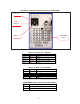
SG2K-2TXI & SG3K-2TX Typical Rear Panel Overview DIP SWITCHES COVER PLATE FOR COMMUNICATIONS SLOT RS-232 CONNECTOR EXTERNAL BATTERY CONNECTOR COVER PLATE COOLING FANS DO NO BLOCK 208-240Vac OUTPUT 208-240Vac RECEPTCALE RECEPTACLE OUTPUT FUSES FOR FUSES THEOUTPUT TOP RECEPTACLE (2) PLACES MAIN POWER POWER SWITCH MAIN SWITCH&& INPUT CIRCUIT INPUT CIRCUIT BREAKER BREAKER BREAAKER 120Vac 120VacOUTPUT OUTPUT RECEPTACLE RECEPTACLES LINE CORD INLET SG2K-2TXI Output Configuration The SG2TXI model provides
CHAPTER 5 COMMUNICATIONS INTERFACES RS-232 INTERFACE Location: The RS-232 interface is standard on all SG series UPS models. The port is located on the UPS rear panel, via a DB-9 female connector.
DRY CONTACT & OPTO COUPLER INTERFACE BOARD OPTIONS Typical Falcon Dry Contact Relay Board DB-9 JP1 JP2 JP3 J1 J2 J3 PIN & JUMPER ASSIGNMENT FOR THE FALCON UA88374 RELAY OPTION BOARD (no on-bypass signal) PIN 1 2 3 4 5 6 7 8 9 DESCRIPTION Low Battery ( When UPS reaches low battery, contact activates) (J1, 1-2 short = N.O) (J1, 2-3 short = N.C) JP2 shorted = Low Battery common & all other shorted JP commons JP2 open = common for low battery only Utility Loss N.O.
Typical Falcon Opto-coupler Interface Card PIN ASSIGNMENT FOR THE FALCON UA88373 OPTO-COUPLER OPTION BOARD (no-bypass signal) PIN 1 2 3 4 5 6 7 8 9 DESCRIPTION Not Used Utility Loss (N.O.) (Closes upon utility loss) Utility Loss (N.C.) (Opens upon utility loss) Common for pins 2, 3 & 5 Low Battery (N.O.
APC Style Dry Contact Relay Board PIN & JUMPER ASSIGNMENT FOR THE FALCON UA88377 RELAY OPTION BOARD (APC Style Board) PIN 1 2 3 4 5 6 7 8 9 DESCRIPTION Remote Shutdown (on battery operation only) Remote Shutdown Common Not Used Low Battery Common Low Battery (N.O.
CHAPTER 6 Maintenance & Technical Support 1. Care & Maintenance Falcon® SG Series UPSs are designed to be maintenance-free. They can be cleaned with a damp cloth or non-abrasive cleanser, providing the UPS is turned off and the input plug is disconnected from the utility source. On a regular basis, check the vents to make sure they are kept free from accumulation of dust, dirt or lint. 2. Battery Life vs. Temperature For full battery life, keep the UPS close to an ambient temperature of 77ºF.
The following precautions should be observed by a qualified technician when working with batteries. 1. 2. 3. 4. Remove watches, rings, or other metal objects. Use tools with insulated handles. Wear rubber gloves and boots. Do not lay tools or metal parts on top of batteries. 4. Storing the UPS and Batteries Should you need to store the UPS for a long period, fully recharge the battery just prior to storage and recharge the battery every 4 months by plugging the UPS into a power outlet.
6. Technical Support Your FALCON® Electric SG Series UPS is backed by one of the finest customer service teams assembled. Write, call, fax or email should you require technical assistance or service. Falcon Electric Inc. 5106 Azusa Canyon Road Irwindale, CA. 91706 Service 800.842.6940 Voice 626.962.7770 Fax 626.962.7720 Email: service@falconups.com WWW.FALCONUPS.COM Please have your UPS model, serial numbers and date of purchase on hand prior to your call.
WARRANTY GENERAL PROVISIONS FALCON® ELECTRIC INC., hereby warrants product shipped under this agreement to be free from defective workmanship for a period of two years following date of shipment. This Limited New Product Warranty Agreement only applies to covered repairs to the product occurring within the United States and Canada. EXCLUSIONS: The following are not covered by the Falcon Electric Limited New Product Warranty: 1.
800VA to 1.5kVA SG SeriesTM UPS PLUS® Model Number Nominal VA SG800-1T 800 SG1K-1T 1000 SG1K-2T 1000 SG1.5K-1T 1500 Electrical Input Nominal AC Voltage AC Voltage Range Current -Amps Frequency Power Factor Correction Efficiency (Typical) 120V 87-140V 5.5 120V 230V 87-140V 170-275V 6.9 3.6 50/60 Hz ± 5% (Auto – Tracking) > 0.95 > 86% 120V 87-140V 10.7 560 100V 110V 115V 120V 700 700 100V 200V 110V 220V 115V 230V 120V 240V 50/60 Hz (Auto Tracking ) ±0.
2kVA & 3kVA SG SeriesTM UPS PLUS® Model Number Nominal VA SG2K-1T SG2K-2T SG3K-1T 2000 SG3K-2T 3000 SG2K-2TXI 2000 SG3K-2TX 3000 Electrical Input Nominal AC Voltage AC Voltage Range Current – Amps Frequency Power Factor Correction Efficiency (Typical) 120V 87 – 140V 14.2 230V 170 – 275V 7.4 120V 230V 87 – 140V 170 – 275V 21.4 11.2 50/60 Hz ± 5% (Auto – Tracking) > 0.95 230V 170 – 275V 7.5 11.