
User manual

64
Traffic-Control
EN
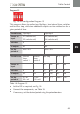
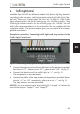
Program 12
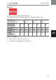
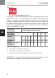
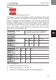
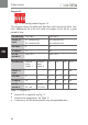
Fig. 17: DIP configuration Program 12
This program allows to realize two flip-flops and two interval timer swit-
ches. Additionally E5 to E8 will switch on outputs A5 to A8 for a given
period of time.
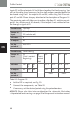
Possible use
Flip-flop 1 Flip-flop 2
Sensor at
input
E1 (switches on)
E2 (switches off)
E3 (switches on)
E4 (switches off)
activates
K K
at output
A1 A3
for the
period of
max. 40 s max. 40 s
Possible use
Interval
timer
switch 1
Interval
timer
switch 2
X 1 X 2 X 3 X 4
Sensor at
input
E5 E6 E7 E8
activates
K K K K K K
at output
A2 A4 A5 A6 A7 A8
for the
period of
5 s on
55 s off
5 s on
115 s off
Poti 1 Poti 2 1 s 10 s
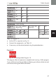
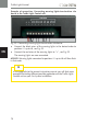
Table 17: Program 12
X
Set the DIP as required, see Fig. 17.
X
Connect the components, see Table 17.
X
If necessary, set the desired period using the potentiometers.