User Instruction Manual DuraTech® 6' Single/Twin Self‐Retracting Device This manual is intended to meet the Manufacturer's Instructions as required by ANSI Z359 and should be used as part of an employee training program as required by OSHA. WARNING This product is part of a personal fall arrest, restraint, work positioning, suspension, or rescue system. A Personal Fall Arrest System (PFAS) is typically composed of an anchorage and a Full Body Harness (FBH), with a connecting device, i.e.
TABLE OF CONTENTS 1. DESCRIPTION 4.7 Locking Speed 1.1 SRD Types 4.8 Installation and Use of the SRD 1.2 Appendices A and B 4.8.1 Single SRD 1.3 ANSI and OSHA 4.8.2 Twin‐leg SRDs 2. APPLICATION 4.8.3 Install the Twin‐SRD 2.1 Purpose 4.8.4 Twin‐leg SRD Work Zone Transition 2.2 Personal Fall Arrest 4.9 Impact Indicator 2.3 Application Limits 5. SPECIFICATIONS 3. SYSTEM REQUIREMENTS 6. MAINTENANCE, SERVICE AND STORAGE 3.1 Capacity 6.1 Maintenance 3.2 Compatibility Of Connectors 6.2 Service 3.
NOTE: Attachment to any anchorage other than directly overhead will require additional fall clearance distance and swing fall clearance. Lateral movement will result in a significant increase to fall clearance distance and swing fall requirements. See Section 4. 2.4 Application Limits: Take action to avoid moving machinery, sharp edges, abrasive surfaces, and thermal, electrical and chemical hazards as contact may cause serious injury or death. DO NOT attach to a foot‐level anchorage.
To avoid an unintended disengagement of connectors, use only compatible connectors when connecting to the anchorage. Ensure all connectors close and lock securely. See Figure 13 in Appendix B. NOTE: OSHA 1926.502 and 1910.66 requires that anchors for a PFAS be able to hold at least 5,000 pounds of weight per person or maintain a safety factor of at least two (twice the impact load) under the supervision of a qualified person. Also ensure the anchor point will provide sufficient MRFC. 4.
The SRD will pay out and retract smoothly to maintain a taut line during normal movement. Work as directly under the anchor as possible. If necessary, the housing end connector may be attached to a lower level anchorage, up to 2 ft. below the user’s harness D‐ring. Be aware that a lower anchorage increases the risk of injury due to swing fall. Additional fall clearance is required. DO NOT use a rebar hook, or any large‐throat snap hook, or large carabiner to connect the leg end to the FBH.
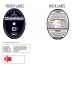
Visual Impact Indicator Label 6
Manual de instrucciones para el usuario Dispositivo autorretráctil doble/individual DuraTech™ de 6 pies (1,8 m) Este manual está destinado a cumplir con las instrucciones del fabricante, según lo requerido por ANSI Z359 y debe utilizarse como parte de un programa de capacitación para empleados según se requiere por la OSHA. ADVERTENCIA Este producto es parte de un sistema personal de detención de caídas, de restricción, posicionamiento del trabajo, suspensión o de rescate.
ÍNDICE 1. DESCRIPCIÓN 1.1 Tipos de SRD 1.2 Apéndices A y B 1.3 ANSI y OSHA 2. APLICACIÓN 2.1 Objetivo 2.2 Detención de caídas personal 2.3 Límites de la aplicación 3. REQUISITOS DEL SISTEMA 3.1 Capacidad 3.2 Compatibilidad de conectores 3.3 Compatibilidad de componentes 3.4 Realizar las conexiones 3.5 Sistema personal de detención de caídas 3.5.1 Fuerza de detención promedio y distancia de detención 3.6 Definiciones 4. INSTALACIÓN Y OPERACIÓN 4,1.
2.3 Orientación del SRD en detención de caídas: El SRD de 6 pies (1,8 m) es un diseño versátil, capaz de opciones de orientación de conexiones múltiples, bien sea como una unidad en una sola pierna, o como una unidad para las dos piernas, como se muestra en las Figuras 2A, 2B y 2C del Apéndice A. 2.3.1 SRD individual: Un SRD con dos opciones de orientación; Como un SRD individual con el extremo de la carcasa conectado al anillo en "D" dorsal de un FBH y el extremo de la pierna conectado a un anclaje.
Persona calificada: Una persona con un título o certificado profesional reconocido y con amplios conocimientos, capacitación y experiencia en la protección contra caídas y el campo de rescate, quien es capaz de diseñar, analizar, evaluar y especificar los sistemas de protección contra caídas y sistemas de rescate en la medida exigida por la norma. Socorrista: Persona o personas distintas al sujeto que actúa en la realización de un rescate asistido por la operación de un sistema de rescate. 4.
NO conecte la unidad a un punto que esté más de 2 pies (0,6 m) por debajo del nivel del anillo en "D" del FBH. 4.7 Velocidad de bloqueo: El SRD utiliza un mecanismo de bloqueo centrífugo. La función de bloqueo requiere una cierta tasa de desenrollamiento durante un evento de caída para que funcione correctamente. Si se produce una caída, se activa un mecanismo de trinquete que aplica un freno de disco, desacelerando y deteniendo la caída.
5. ESPECIFICACIONES Consulte las Tablas 1A, 1B, y 1C en el Apéndice A. 6. MANTENIMIENTO, SERVICIO Y ALMACENAMIENTO 6.1 Mantenimiento: Mantenga el SRD libre de contaminantes, tales como pintura, grasa, grava y químicos, ya que pueden obstaculizar las funciones de la cuerda de salvamento. Evite que la suciedad entre en la carcasa a través del puerto de la cuerda de salvamento. Limpie el exterior de la unidad según se requiera con una solución de agua y jabón. No permita que entre agua dentro de la carcasa.
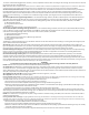
APPENDIX A Table 1A: Specifications for 6 ft Web SRDs SRD Configuration and Part Numbers Twin Leg SRDs: 82706TB1 82706TB2 82706TB3 82706TB4 82706TB5 82706TB6 Minimum Tensile Strength and Material Webbing: 4,500 lbs 80% Dyneema 20% Polyester 20mm width 82706SA1 82706SA2 82706SA3 82706SA4 82706SA5 82706SA6 82706SB1 82706SB2 82706SB3 82706SB4 82706SB5 82706SB6 82706SD1 82706SD3 82706SE2 82706SF4 82706SF6 82706SG5 82706SG6 SRD Housing: Polycarbonate with 30% glass Main Shaft: Alloy Steel Standards/ Perform
Table 1B: Specifications for Single-leg Swivel Eye Connectors Part # Reference Connector Housing Swivel Eye Connector Material Gate Opening All Anchorage Connectors shown below have 5,000 lb Minimum Tensile Strength and 3,600 lb minimum Gate Strength to comply with ANSI Z359.12 A Integral Housing Swivel Eye only Aluminum Hole: .37” B Carabiner with Capti e Pin Steel .95” D* Snap Hook Steel .85” E* Rebar Hook Steel 2.5” F* Rebar Hook Aluminum 2.
Table 1C: Specifications for SRD Leg-end Connectors Part # Reference Leg-End Connector Connector Material Gate Opening All Anchorage Connectors shown below have 5,000lb Minimum Tensile Strength and 3,600lb minimum Gate Strength to comply with ANSI Z359.12 1 Snap Hook Steel .85” 2 Swivel Snap Hook Steel .85” 3 Rebar Hook Steel 2.5” 4 Snap Hook Aluminum .8” 5 Rebar Hook Aluminum 2.5” 6 Capti e Eye Carabiner Aluminum .
Table 1D: Part Numbers with Connector Reference 1 2 3 (2) 4 5 (2) Alum. Captive-Eye Carabiner G Aluminum Rebar Hook F (1) Aluminum Snap Hook E (1) Steel Rebar Hook D Steel Swivel Snap Hook Steel Rebar Hook (B) Steel Snap Hook Steel Snap Hook B Leg-End Connectors Alum.
Tabla 1D: Números de partes con referencia del conector E (1) F (1) 3 (2) 4 5 (2) 82706SA1 82706SA2 82706SA3 (2) 82706SA4 82706SA5 (2) 82706SA6 82706SB1 82706SB2 82706SB3 (2) 82706SB4 82706SB5 (2) 82706SB6 82706SD1 82706SD3 82706SE2 82706SF4 82706SF6 (2) (1) (1) (1) 82706SF4 (2) 82706SF6 Mosquetón con ojal cautivo en aluminio 2 Gancho de refuerzo en aluminio 1 Gancho de cierre instantáneo en aluminio G Gancho de refuerzo en acero Gancho de cierre instantáneo con eslabón en acero D
Type of Use Application Examples Conditions of Use Inspection Frequency Competent Person Infrequent to Light Rescue and Confine Space, Factory Maintenance Good Storage Conditions Indoor or Infrequent Outdoor Use, Room Temperature, Clean Environments Annually Moderate to Heavy Transportation Residential Con truction Utilities, arehouse Fair Storage Conditions, Indoo And Extended Outdoor Use, All Temperatures, Clean or Dusty Environments Semi-annually to Annually Severe to Continuou Harsh Storage
Table 3: Guidelines for SRD Inspection (use Figure 1 where needed) Inspection Pass Fail The web lifeline should extract and retract completely and without faltering and should remain taut under tension without sagging. Extract the web lifeline several inches and apply a firm pull o confirm the SRD locks. The locking should be certain and without skidding. Repeat this lockup at additional places along the li eline length to confirm the SRD is operating orrectly.
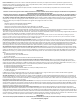
F6SRD2.1 1: Carabiner Body 2: Triple-Lock Gate 3: Alignment Clip 1: Cuerpo del mosquetón 2: Pestillo de bloqueo triple 3: Sujetador de alineación Fig. 1: About 6’ Self-Retracting Devices A Integral Swivel Eye E B Unit Housing F* Integral Stirrup Connec or C Load Indicator Sti ch G Triple-lock Carabiner D Web Lifeline H Alignment Clip Leg-end Connector *Stirrup Connector on some single-leg models only; see Table 1B Fig.
Fig. 2A: Orientación del SRD y rango aceptable del anclaje Single-leg SRD mounted to Dorsal D-ring SRD individual montado en el anillo en “D” dorsal T6SRD3.1 D6SRD3.4 Fig. 2A: SRD Orientation and Acceptable Anchorage Range = Rango de conexión permisible de: Directamente por encima de la cabeza a tan bajo como a 2 pies (0,6 m) por debajo del anillo en “D” dorsal Fig. 2B: SRD Orientation and Acceptable Anchorage Range Fig.
D6SRD7.1 Fig. 3A: Minimum Required Fall Clearance- 6’ SRD Overhead (Above Dorsal D-ring) Anchorage Condition A 2½ B 1 C 1½ D 5 SRD Deceleration Distance D-ring shift and harness stretch Safety factor Total Fall Clearance Required 1. Overhead Anchorage 2. Walking/Working Surface 3. Nearest Lower Level or Obstructio If a potential Swing Fall Hazard condition is also present, additional Fall Clearance is needed in the above calculation; see Chart 1 for calculating this additional required distance.
D6SRD9.1 Fig.
6’ 6’ 6’ 6’ 6’ 0’ 0’ 0’ 6’ 6’ 6’ 6’ 6’ 5’ 6’ 6’ 6’ 1’ 0’ 0’ 0’ 0’ 0’ 1’ 6’ 6’ 6’ 4’ 6’ 6’ 2’ 1’ 0’ 0’ 0’ 0’ 0’ 1’ 2’ 6’ 6’ 3’ 6’ 3’ 2’ 1’ 1’ 0’ 0’ 0’ 1’ 1’ 2’ 3’ 6’ 2’ 6’ 3’ 2’ 2’ 1’ 0’ 0’ 0’ 1’ 2’ 2’ 3’ 6’ 1’ 5’ 4’ 3’ 2’ 1’ 0’ 0’ 0’ 1’ 2’ 3’ 4’ 5’ 0’ 6’ 5’ 4’ 3’ 2’ 1’ 0’ 1’ 2’ 3’ 4’ 5’ 6’ -1’ 6’ 5’ 4’ 3’ 2’ 1’ 0’ 1’ 2’ 3’ 4’ 5’ 6’ -2’ 6’ 5’ 4’ 3’ 2’ 1’ 0’ 1’ 2’ 3’ 4’ 5’ 6’ C6SRD13 6
6’ 6’ 6’ 6’ 1’ (0,3 m) 1’ (0,3 m) 1’ (0,3 m) 2’ (0,6 m) 2’ (0,6 m) 3’ (0,9 m) 3’ (0,9 m) 3’ (0,9 m) 0’ (0,0 m) 0’ (0,0 m) 1’ (0,3 m) 1’ (0,3 m) 1’ (0,3 m) 2’ (0,6 m) 2’ (0,6 m) 2’ (0,6 m) 2’ (0,6 m) 2’ (0,6 m) 2’ (0,6 m) 3’ (0,9 m) 4’ (1,2 m) 4’ (1,2 m) 4’ (1,2 m) 0’ (0,0 m) 0’ (0,0 m) 0’ (0,0 m) 0’ (0,0 m) 0’ (0,0 m) 0’ (0,0 m) 1’ (0,3 m) 1’ (0,3 m) 1’ (0,3 m) 0’ (0,0 m) 0’ (0,0 m) 0’ (0,0 m) 0’ (0,0 m) 0’ (0,0 m) 0’ (0,0 m) 0’ (0,0 m) 0’ (0,0 m) 0’ (0,0 m) 0’ 6’ (0,0 m) 0’ 0’ (0,0 m) (0,0 m) 0’ 0
D6SRD10.2 Fig. 5A: Attaching Single-leg SRD to FBH A Leg End Connector B Web Lifeline C SRD Body/Housing D SRD Integral Swivel Eye E Carabiner w/captive pin F Dorsal D-ring on FBH Conector del extremo de la pierna B Cuerda de salvamento C Cuerpo/carcasa del SRD D Ojal de oscilación integral del SRD E Mosquetón con pasador cautivo F Anillo en “D” dorsal en el FBH D6SRD14.2 A T6SRD10 Fig. 5A: Conectar un SRD individual a un FBH Fig.
1. Prepare Twin-leg SRD for Attachment (A) (B) (C) (D) 2. Prepare FBH and Preliminary Attachment (E) (F) (G) 2. Prepare FBH and Preliminary Attachment: (E) Lift the Dorsal D-ring to the up-pointing position then loosen the tersection of the two web straps that pass through the D-ring slot to create slacked loops of about 2” or 3”.
1. Preparar el SRD doble para la conexión (A) (B) (C) (D) 2. Preparación del FBH y conexión preliminar (E) (F) (G) 2. Preparación del FBH y conexión preliminar: (E) Levante el anillo en “D” dorsal hasta la posición de señalización hacia arriba, luego afloje la i tersección de las dos correas que pasan por la ranura del anillo en “D” para crear lazos holgados de alrededor de 2” (5,08 cm) o 3” (7,6 cm).
INCORRECT INCORRECT INCORRECT CORRECT Fig. 6B: Incorrect Twin-leg SRD Attachment DO NOT Attach directly to the Dorsal D-ring B DO NOT Attach to only one of the intersecting web straps C DO NOT Attach to intersecting web straps over/above the Dorsal D-ring D DO NOT Attach anywhere outside the intersecting web straps E CORRECT attachment to both intersecting web straps with Dorsal D-ring in the up position INCORRECTA CORRECTA INCORRECTA D6SRD12.2 INCORRECTA Fig.
B Before Lateral Movement Starting Lateral Movement C Momentary Transition D Ending Lateral Movement E After Lateral Movement D6SRD18 A Fig.
APPENDIX B Fig.
Fig.
Fig.
Common Fall Protection Applications Fig. 7 - Fall Arrest (PFAS) Fig. 8 - Work Positioning Positioning Anchor Anchorage Connector A B C Shock Absorbing Lanyard (SAL) C Full Body Harness (FBH) with Side D-Rings D Full Body Harness (FBH) E D Back-up Fall Arrest (PFAS) Walking/Working Surface Fig. 8 - Posicionamiento del trabajo Arnés de cuerpo completo (FHB) E Superficie para caminar/trabajar DUFPA1.1 TUFPA1.
DUCON.2 Incorrect Connections / Acronyms for Fall Protection and Fall Arrest / Inspection Record C D E F G A B C D E Never attach in a manner where an element of the connector (gate or release lever) may become caught on the anchor thereby producing additional risk of false engagement. Never attach a spreader snap hook to two side/positioning D-rings in a manner whereby the D-rings will engage the gates; the gates on a spreader must always be facing away from the D-rings during work positioning.
FallTech 1306 South Alameda Street Compton, CA 90221, USA 1‐800‐719‐4619 1‐323‐752‐0066 www.FallTech .