
User Manual


PART 1: HOOD INSTALLATION GUIDE - INTEGRATED HOODS - ON BOARD MOTOR
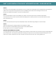
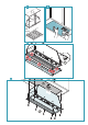
STEP 4:
The returns on the main body are now exposed. These are used to fix the main body on to the cabinetry. Place the hood in the
cabinet in the level position ensuring that the controls and display will be visible when standing in front of the unit.
Using the pre-drilled mounting holes, screw the hood into position.
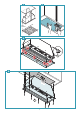
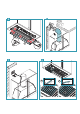
STEP 5:
Once the main body is secure into the cabinetry the stainless steel fascia can then be slid inside the main body.
The fascia will cover the screws that have fixed the main body into the cabinetry. Place the screws back into place which
were removed in step 3.
STEP 6:
Connect the hood outlet (in the top or back ducted position) to 150 mm ducting leading to an external output.
STEP 7:
Attach the male plug of the rangehood unit to the main power supply.
Note to electricians: Standard 10 amp general power outlet (GPO) required.
Position GPO as close to the hood unit as possible.
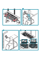
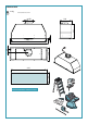
GREASE TRAP AND BAFFLE FILTERS:
The integrated range of hoods utilize a removable grease trap that is used to catch excess amounts of grease and condensate
from the baffle filters. This trap can be removed for cleaning. The trap consists of a concave channel with fixing points in the
channel of the trap. The baffle filters will then sit within the channel, with the filter vanes running downward.